natshaw wrote:Hope it's SCART with RGB! Have had SCART before that doesn't implement full spec, or does odd stuff like using component in via the RGB pins etc. If you wire up those voltage signals onto SCART also, you'll get auto-input selection if the TV supports it.
Ta - I'll let you know once I've had time to pick it up and have a play.
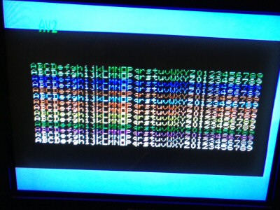
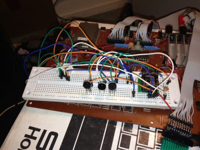
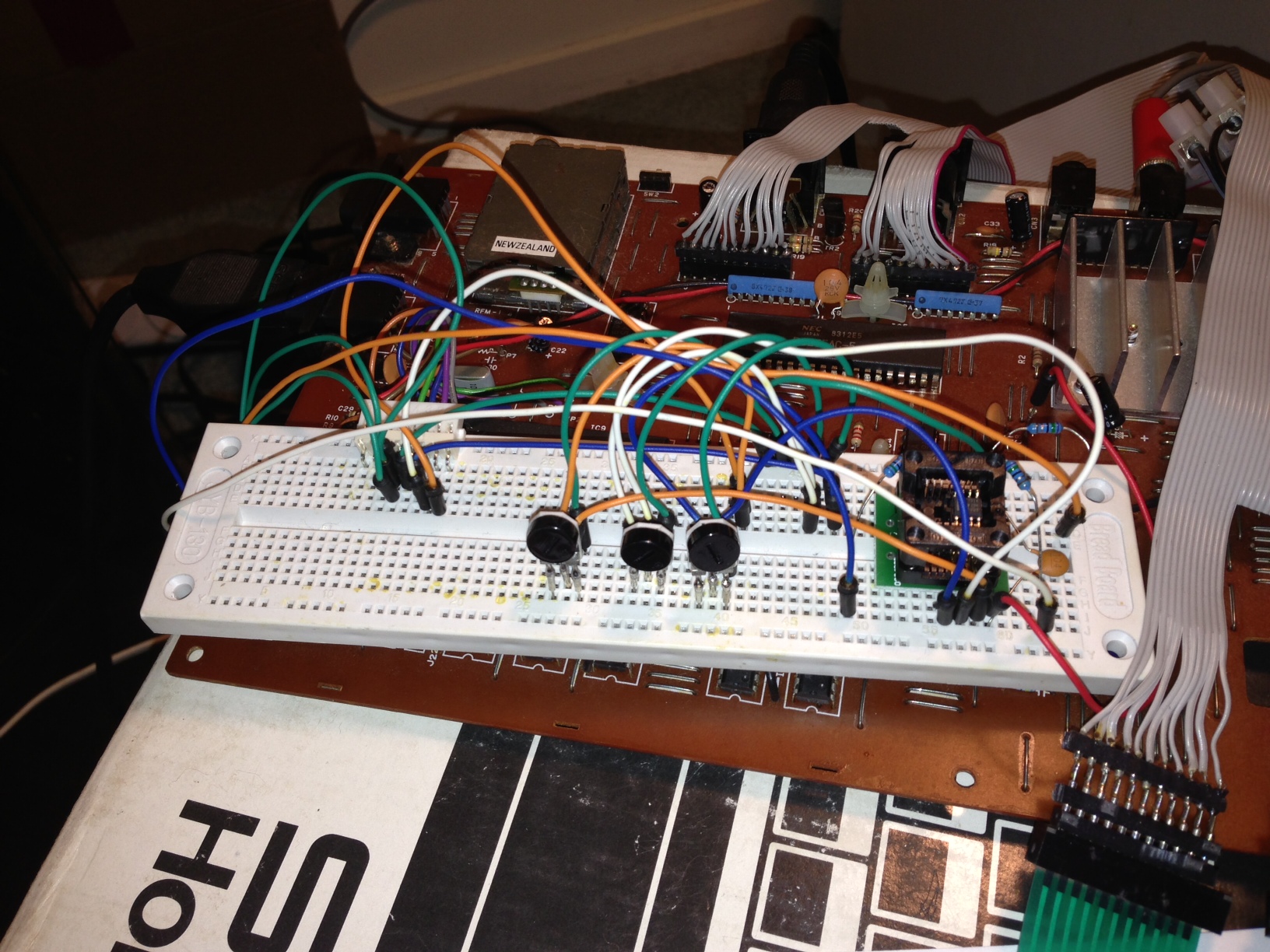
Progress update and some notes for future reference. These are the measured resistance levels at the trim pots feeding from the TMS9929A daughterboard connector to the THS7314 buffer amplifier after I adjusted them on my test pattern to get a reasonable balance. The trim pots basically form a voltage divider which scale the output from the TMS9929A. Note that the trim pot resistance levels can vary quite a bit, but I don't think that is critical for this application.
R-Y Trim Pot
535 Ohms to ground
345 ohms to wiper
so should be 190 ohms from wiper to ground (not checked)
So that scales the input to the amp by 190/535 = 0.355 (that is then multiplied by 2 by the amp = 0.71 * original signal)
B-Y Trim Pot
473 ohms to ground
376 ohms to wiper
so should be 97 ohms from wiper to ground (not checked)
So that scales the input to the amp by 97/473 = 0.205 (that is then multiplied by 2 by the amp = 0.41 * original signal)
Y Trim Pot
545 ohms to ground
342 ohms to wiper
so should be 203 ohms from wiper to ground (not checked)
So that scales the input to the amp by 203/545 = 0.372 (that is then multiplied by 2 by the amp = 0.744 * original signal)
(edited initial copy-paste error in above - oops)
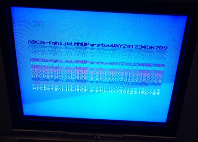
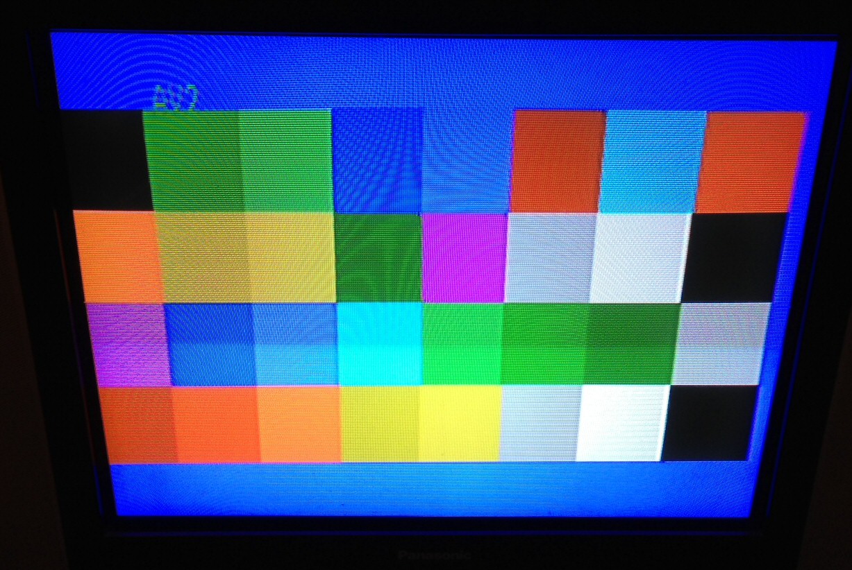
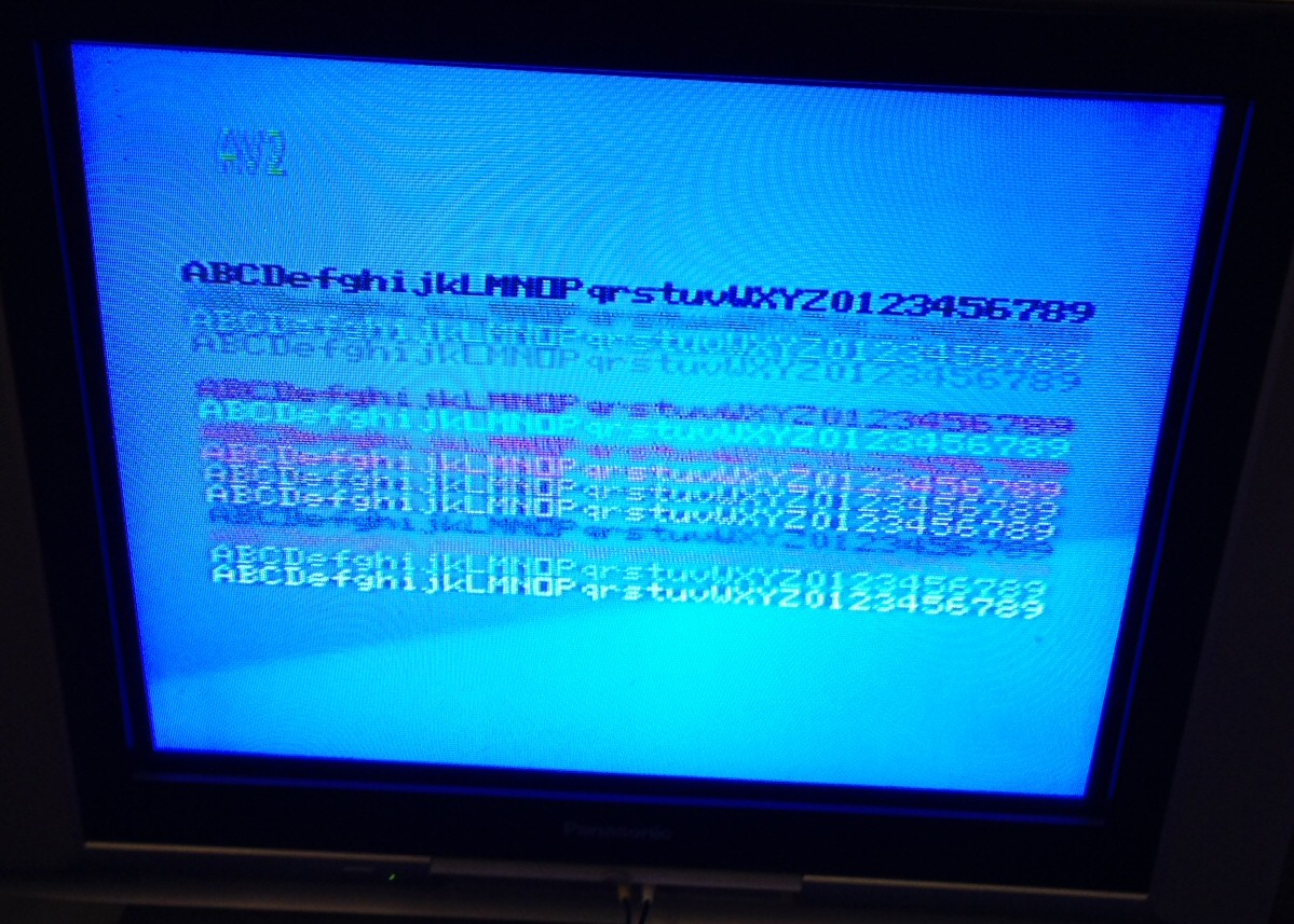
As expected (from 5-11under's work), we have to scale B-Y back by more than R-Y and Y to get rid of the overly blue default picture. And as expected, I'm getting washed out yellows. So I tried using the AD830 to subtract some Y from the scaled B-Y signal. In 5-11under's notes he says to adjust B-Y, then R-Y and Y to suit, then try adjusting the -Y pot. You should be able to see more saturated yellows before the white starts yellowing out. But in my setup the white starts to go to green at the same time the Yellows start to saturate more. So something isn't quite right there. I haven't tried the -Y correction to the R-Y yet, but that should be minimal as that is scaled to approximately the same level as Y from my measurements above.
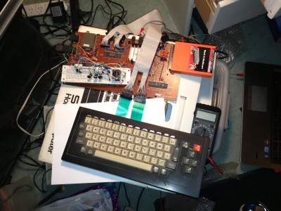
I hooked the AD830 in by powering it off the 9v feed from the daughterboard connector (you need 8v minimum if using a single supply, so 9v is fine). The amplified Y signal is fed to a trim pot to ground with the wiper connection going to pin 2 of the AD830. The amplified B-Y signal goes to the AD830, then I'm driving the Pb line to the TV from the AD830 output. (check the datasheet for rest of wiring - you loop the output from pin 7 back to pin 4 and wire pin 3 to ground).
I'll probably try an Op Amp based approach using the AD828s next to see how that compares with the THS7314. It sure is handy not having to use a whole pile of extra resistors though

I also have an original component video output SC-3000 hooked up to the same TV with a multicart so I can quickly switch between the before / after views to see how well my mod compares. So far, the component video gives better resolution, and better performance on allowing colours to stay seperated (composite fails miserably when you have small areas of reds and yellows / whites together on black for instance, and some other colour combinations are bad too). But I can't match the nice bright well balanced test pattern I can get on the original composite feed yet, so still some work to do. Having said that, my composite view has the TV colour boosted up to maximum and component is only at 50%, but the difference in the yellows and whites is still very noticeable on the large colour blocks in the test pattern and much better on the original composite feed).
Here's a nice summary of what ideal test signals should look like for YPbPr and NTSC
http://www.matrixav.com/reference/various_signals.htmand here's a nice primer on video standards and how the voltage levels and black / blanking levels vary
http://www.avc.com.hr/eurostar/Teh_Podr ... erview.pdfCheers
