TMS9929 (Sega etc.) display direct to modern TV!

Seek advice, give advice or tell others about your repair and restoration projects

Re: TMS9929 (Sega etc.) display direct to modern TV!

Postby honestbob on Mon Apr 15, 2013 9:19 am

natshaw wrote:
honestbob wrote:So that scales the input to the amp by 203/545 = 0.732 (that is then multiplied by 2 by the amp = 0.744 * original signal)

or 1.464?


oops - the error was in the first half of equation. Fixed initial posts above to

So that scales the input to the amp by 203/545 = 0.372 (that is then multiplied by 2 by the amp = 0.744 * original signal)

natshaw wrote:I've done a bit more working out of the RGB values implicit in the VDP's YPrPb tables in the datasheet. Starting to make sense now, will post details later today.


Looking forward to that. I did a bit of reading on the different colour difference scalings applied under various video standards over the weekend, but I haven't quite got it yet. In particular I was trying to figure out the appropriate transformation to get the green channel information from YPbPr to explain why my 'subtract more Y' mod just turns the whites and yellows green rather than saturating them more as per 5-11under's notes. I'm obviously missing something there...
honestbob
 
Posts: 92
Joined: Thu Jan 05, 2012 8:21 am
Location: New Zealand

Re: TMS9929 (Sega etc.) display direct to modern TV!

Postby natshaw on Tue Apr 16, 2013 10:35 am

Dumb question - if you adjust the Y trimpot, do you get any change of tint at all?
SC-3000H, SC-3000H, Amiga 500. Hobbyist electronics and programming.
natshaw
 
Posts: 69
Joined: Sat Feb 16, 2013 9:44 pm

Re: TMS9929 (Sega etc.) display direct to modern TV!

Postby natshaw on Tue Apr 16, 2013 11:07 am

Hmm, something not right with the YPbPr levels in the TMS9929 datasheet. In theory, the PbPr true value is offset by .47, presumably for ease of handling in a single-supply circuit.

Once you offset that, and then apply the YPbPr to RGB formulas, the numbers look about right, but are not. Some colour levels exceed those seen in the white colour. Looks wrong to me.

Code Colour R G B Y Pb Pr Pb-.47 Pr-.47
1 BLACK 0% 0% 0% 0.00 0.47 0.47 0.00 0.00
2 Med green 13% 91% 5% 0.53 0.20 0.07 -0.27 -0.40
3 Lt green 37% 95% 32% 0.67 0.27 0.17 -0.20 -0.30
4 Dk blue 33% 27% 134% 0.40 1.00 0.40 0.53 -0.07
5 Lt blue 49% 40% 135% 0.53 0.93 0.43 0.46 -0.04
6 Dk red 83% 27% 17% 0.47 0.30 0.83 -0.17 0.36
7 Cyan 26% 99% 114% 0.73 0.70 0.00 0.23 -0.47
8 Med red 99% 27% 18% 0.53 0.27 0.93 -0.20 0.46
9 Lt Red 113% 41% 32% 0.67 0.27 0.93 -0.20 0.46
10 Dk yellow 83% 80% 2% 0.73 0.07 0.57 -0.40 0.10
11 Lt yellow 90% 83% 27% 0.80 0.17 0.57 -0.30 0.10
12 Dk green 13% 80% 4% 0.47 0.23 0.13 -0.24 -0.34
13 Magenta 79% 28% 88% 0.53 0.67 0.73 0.20 0.26
14 Grey 80% 80% 80% 0.80 0.47 0.47 0.00 0.00
15 White 100% 100% 100% 1.00 0.47 0.47 0.00 0.00

Calculation used: R = Y + 1.402 * Pr
G = [Y] - 0.344136 * [Pb] - 0.714136 * [Pr]
B = [Y] + 1.772 * [Pb]
SC-3000H, SC-3000H, Amiga 500. Hobbyist electronics and programming.
natshaw
 
Posts: 69
Joined: Sat Feb 16, 2013 9:44 pm

Re: TMS9929 (Sega etc.) display direct to modern TV!

Postby natshaw on Sat Apr 20, 2013 2:51 am

I do not think any voltage gain is required. I think my previous measurements of the output voltages were not taken using a white signal.

Have been doing further digging. I have answers, and questions. I think use of op-amp (or just a common collector transistor) is required, but it is only current gain that is required. I.e. a voltage-follower buffer (1x gain, that is ~same volts out as in) circuit that presents as 470 ohms impedance, and drives 75+ ohms impedance (your telly). So, a regular op-amp would have VDP's signal into (+), and op-amp's own output into (-), to give 1x gain. That's about it.

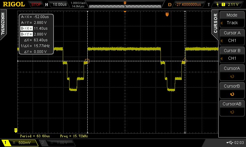
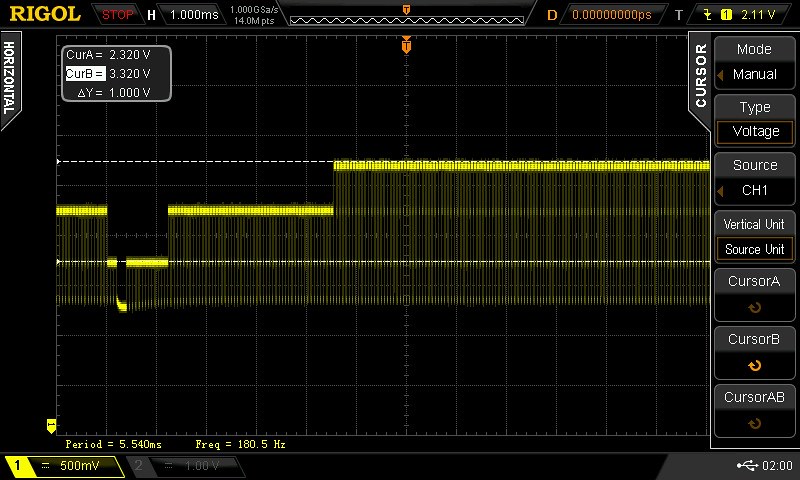
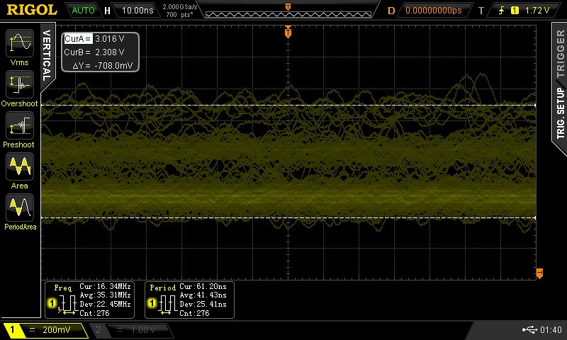
Why do I think this? Take a look at this scope image of the VDP's luma output pin for a single scanline (graphics mode 1, white background, blue border) from the TMS9929 in a Sega SC-3000, it is already at sufficient voltage! Each division is half a volt, so you can see this peak-to-peak range is about 1.3V. Longest part is the white, then stepping down to blue either side of that, then blank either side, and separated by a sync pulse. Second image shows more scan lines overlaid each other. I've put horizontal lines about 1 volt apart, you can see the sync pulses about 0.3V below the bottom line. I know 1.3 is over the typical 1.0 used these days, but I think I read that was the old (non consumer?) standard, and many devices will accept it. Also included image of Pb line, showing voltage range is a bit over the typical 0.7V range.

Once scanline:
Image
Lots scanlines:
Image
Pb line:
Image
SC-3000H, SC-3000H, Amiga 500. Hobbyist electronics and programming.
natshaw
 
Posts: 69
Joined: Sat Feb 16, 2013 9:44 pm

Re: TMS9929 (Sega etc.) display direct to modern TV!

Postby honestbob on Fri Jun 07, 2013 9:53 pm

Hi All

Nice to have the forums back up again - thanks Tezza :)

It has been a while, but I've still been working on this. Been hell busy at work and my wife has been ill, unfortunately. Anyway, here's a long and detailed analysis of progress with a summary at the top.

Summary
I can now make sense of the TMS9929A datasheet and the voltage levels for Y, B-Y, and R-Y. I know how they calculated the values in table 2-3 on page 2-17 of the datasheet (see earlier discussion above where the numbers didn't quite add up), and they fit with measurements taken on the Rigol 1052E oscilloscope I bought off Natshaw. That scope is a very cool piece of kit - love it, thanks :)

The TMS9929A Y output has a 1 volt range from the black voltage level to the white voltage level with the sync tip 0.44 volts below black. So we have 1.44v peak to peak which has to be scaled by approximately a factor of 0.7 to fit the standard voltage range for component video. The B-Y and R-Y outputs also appear to be based on a 1v peak to peak range (no horizontal sync). At the least these also need to be scaled by a factor of 0.7 to fit the standard voltage range for component video.

However empirical testing says that we need additional scaling, otherwise the B-Y signal is far too strong. I'm still not certain about the correct scaling factor to apply to the TMS9929A VDP B-Y and R-Y outputs to get a natural colour balance, but I have a much better understanding of component video now and I have some ideas about what to try next.

There is a good Texas Instruments document that suggests how to build circuits for interfacing the TMS99XXA to composite and RGB monitors, and under RGB it talks about dividing B-Y by 2.03 (ie. multiply by 0.493) and dividing R-Y by 1.14 (ie. multiply by 0.877)

http://spatula-city.org/~im14u2c/vdp-99 ... nitors.pdf

That is consistent with comments in

http://m.broadcastengineering.com/infra ... deo-basics

It strikes me that it *may* be critical to perform DC restoration on the signal prior to scaling, and that *may* be the reason for the poor colour balance, because the DC offset will be altered for the B-Y channel in relation to the Y channel as we scale the B-Y channel by more than the Y channel. That may result in issues for the TV sets as they try to determine the zero level of the incoming component signals.

Here are some useful voltage measurements for reference:

    Vwhite = 3.34v
    Vblack = 2.36v (so approx 1v from Vblack to Vwhite)
    Vsync = 1.92v (so Y channel is approx 1.44v peak to peak)
    Vno_color = 2.80v (B-Y) or 2.84v (R-Y)
    Vb-y 100% = 3.32v
    Vr-y 0% = 2.38v

    Note - I have NOT measured Vb-y 7% (from a dark yellow screen) or Vr-y 93% (from a medium red screen) yet

Analysis:

I've figured out how the TMS9929A voltage specs and colour assignments in Table 2-3 of the TMS99XXA manual work. This is the table that Natshaw referred to earlier:
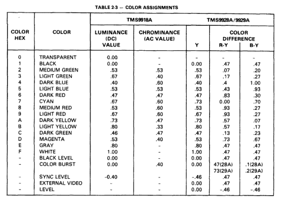
Image

We couldn't figure out how those colour difference voltage levels added up before. Check out the table below for the answer.

I started with the colour levels that the MESS emulator uses. I figured these should be pretty close to accurate as there have obviously been some very talented people working on that over the years. I took a screenshot of my colour test screen and grabbed the RGB values (0..255). I then scaled those to the range of 0 to 1 by dividing by 255 (see R' G' B' columns below).

Image

We then look at the standard colour difference transformations.

Y = 0.299R' + 0.587G' + 0.114B'

Those all match the Y value from Table 2-3 above apart from Light Red, which is slightly out. So either the emulator writers made a mistake, or the TMS99XXA datasheet has an error. I don't know which.

The Pb / Pr columns above use the SCALED transformations where Pb / Pr are mapped to a range of -0.5 to + 0.5. That is what Natshaw tried earlier. But that is NOT what the TMS9929A outputs. The TMS9929A outputs B-Y and R-Y, which is the UNSCALED transformation where B-Y ranges from +/- 0.886 and R-Y ranges from +/- 0.701. So:

B-Y = -0.299R' - 0.587G' + 0.886B'

R-Y = 0.701R' - 0.587G' - 0.114B'

You then offset that by 0.47v and the values match the color difference columns of Table 2-3 exactly (apart from Light Red for which either the MESS emulator or the TMS99XXA documentation is wrong). The offset is there because these are colour differences, and the difference can be either positive or negative. So that 0.47v offset just sticks all the B-Y and R-Y voltages in a nice 1 volt range with the middle of the range around 0.47v above the black level.

ie. in the spreadsheet above, the Y column, B-Y+0.47 column, and the R-Y + 0.47 column all match the contents of Table2-3 above

So now we understand the calculations in the TMS9929A documentation. Those seem to fit reasonably well with observing the actual voltage levels. The oscilloscope has been brilliant for that. Here are some useful numbers:

    Vwhite = 3.34v
    Vblack = 2.36v
    Vsync = 1.92v
    Vno_color = 2.80v (B-Y) or 2.84v (R-Y)
    Vb-y 100% = 3.32v
    Vr-y 0% = 2.38v

    Note - I have NOT measured Vb-y 7% (from a dark yellow screen) or Vr-y 93% (from a medium red screen) yet

The difference in voltage levels from black to white is very close to 1 volt for both the Y and B-Y outputs, which is what it is supposed to be according to the TMS9929A documentation (I haven't verified the voltage range for the R-Y output yet). And the horizontal timings (eg. length of sync pulse, front porch, back porch etc). match the TMS9929A specs almost exactly.

So the output is almost exactly 1 volt peak to peak for the Y, R-Y, and B-Y channels, with -0.44v for the sync signal. That scales nicely down to the European standard of 0.7v peak to peak for the signal plus 0.3v for the sync like so:

1 / 1.44 = 0.694v (for signal) and 0.44 / 1.44 = 0.305v (for sync).

That is close enough to correct allowing for some measurement errors. So we need to adjust our voltage dividers for the luminance channel to hit a 1/1.44 = approx 0.7 multiplier on the original signal level. That is close to the value of 0.744 I came up with empirically on page 4 of the classic computers thread (ie. by turning the trimpot until I got the best balance I could get).

But what about the other two channels? A 0.7 multiplier would also adjust them to 700mV peak to peak. But that isn't consistent with my earlier empirical testing. There I had a 0.41 multiplier on B-Y and 0.71 multiplier on R-Y. And we know from 5-11under's work and my own testing that the B-Y channel is 'too strong' by default.

So that's the final bit of the puzzle. I'm not sure how we are 'supposed' to scale the TMS9929A B-Y signal to meet the correct range for component video input. I've read a number of articles regarding additional scaling factors for B-Y and R-Y, but I'm not yet sure how they apply.

eg. Take a look at http://m.broadcastengineering.com/infra ... deo-basics

That suggests that NTSC / PAL has a 0.493 scale factor on B-Y and 0.877 on R-Y, and EBU-N10 has a 0.564 scale factor on B-Y and 0.713 on R-Y. But I'm not sure exactly at what point you are supposed to apply those factors, nor whether it means that you calculate B-Y and R-Y as above then just multiply again by these factors.

So... I will probably try a couple of approaches. I will try setting the trim pots that feed my THS7314 to values based on the above, then turn the computer on and see what the output looks like.


(As an interesting side note, the early voltage levels used for monochrome composite video had 1.4v peak to peak with 1v for the luminance and -0.4v for the sync. It was later reduced to 1v peak to peak including sync for NTSC, but the 10:4 ratio between signal and sync was kept, which is why NTSC has 714mV peak to peak for the signal and -286mV for the sync. The Europeans decided to make their lives easier by standardizing on a 7:3 ratio which is where the 700mV and -300mV for sync comes from. See attached VideoStandardOverview.pdf for some background reading on that, and the Engineer's Guide to Decoding and Encoding has some interesting material too.)


Measurements for future reference

Remember there will be slight measurement errors in these, but they confirm the TMS9929A specs quite nicely.

Screen set to white (color 15, 15)

    Y Active = 3.34v
    Y Back Porch / Front Porch = 2.36v
    Y Sync = 1.92v

    B-Y Active = 2.80v
    B-Y No Color = 2.80v
    B-Y Vneg (color burst) = 2.52v

    R-Y Active = 2.84v
    R-Y No Color = 2.84v
    R-Y Vpos (color burst) = 3.12v

    Based on 1v peak to peak, TMS9929A specs predict
      Y = 2.36v + 1v = 3.36v (close enough - measured as 3.34v)
      B-Y = 2.36v + 0.47v = 2.83v (close enough - measured as 2.80v)
      R-Y = 2.36v + 0.47v = 2.83v (close enough - measured as 2.84v)

Screen set to black (color 1,1)

    Y Active = 2.38v
    Y Back Porch / Front Porch = 2.38v
    Y Sync = 1.92v

    B-Y Active = 2.80v
    B-Y No Color = 2.80v
    B-Y Vneg (color burst) = 2.52v

    R-Y Active = 2.84v
    R-Y No Color = 2.84v
    R-Y Vpos (color burst) = 3.12v

    Based on 1v peak to peak, TMS9929A specs predict
      Y = 2.38v + 0v = 2.38v
      B-Y = 2.38v + 0.47v = 2.85v (close enough - measured as 2.80v)
      R-Y = 2.38v + 0.47v = 2.85v (close enough - measured as 2.84v)


Screen set to cyan (color 1,7)

    Y Active = 3.08v
    Y Back Porch / Front Porch = 2.36v
    Y Sync = 1.92v

    B-Y Active = 3.02v
    B-Y No Color = 2.80v
    B-Y Vneg (color burst) = 2.52v

    R-Y Active = 2.38v
    R-Y No Color = 2.84v
    R-Y Vpos (color burst) = 3.12v

    Based on 1v peak to peak, TMS9929A specs predict
      Y = 2.36v + 0.73v = 3.09v (close enough - measured as 3.08v)
      B-Y = 2.36v + 0.70v = 3.06v (close enough - measured as 3.02v)
      R-Y = 2.36v + 0v = 2.36v (close enough - measured as 2.38v)

Screen set to dark blue (color 1,4)

    Y Active = 2.76v
    Y Back Porch / Front Porch = 2.36v
    Y Sync = 1.92v

    B-Y Active = 3.32v
    B-Y No Color = 2.80v
    B-Y Vneg (color burst) = 2.52v

    R-Y Active = 2.76v
    R-Y No Color = 2.84v
    R-Y Vpos (color burst) = 3.12v

    Based on 1v peak to peak, TMS9929A specs predict
      Y = 2.36v + 0.4v = 2.76v (exact)
      B-Y = 2.36v + 1.0v = 3.36v (close enough - measured as 3.32v)
      R-Y = 2.36v + 0.4v = 2.76v (exact)


Screen set to light green (color 1,3)

    Y Active = 3.02v
    Y Back Porch / Front Porch = 2.36v
    Y Sync = 1.92v

    B-Y Active = 2.58v
    B-Y No Color = 2.80v
    B-Y Vneg (color burst) = 2.52v

    R-Y Active = 2.56v
    R-Y No Color = 2.84v
    R-Y Vpos (color burst) = 3.12v

    Based on 1v peak to peak, TMS9929A specs predict
      Y = 2.36v + 0.67 = 3.03v (close enough - measured as 3.02v)
      B-Y = 2.36v + 0.27v = 2.63v (close enough - measured as 2.58v)
      R-Y = 2.36v + 0.17v = 2.53v (close enough - measured as 2.56v)
honestbob
 
Posts: 92
Joined: Thu Jan 05, 2012 8:21 am
Location: New Zealand

Re: TMS9929 (Sega etc.) display direct to modern TV!

Postby honestbob on Tue Jun 11, 2013 10:53 am

Further thoughts regarding correspondence from natshaw in email. I'm trying to keep the interesting stuff in a public forum for future reference. Interesting is a relative term of course :)

natshaw wrote:It's interesting that the acceptable range of Y,Pb,Pr voltages (output from VDP) is so wide (min & max vs. nominal) - am I reading that correctly? Hmmm…I suspect it's the usual story, and whatever DC offset is there is expected to be stripped by next stage.


I *think* the idea is that depending on how you load your circuit (ie. circuit design), and depending on things like the temperature (operating free-air temperature range 0c to 70c), then the voltages output by the VDP could slide up and down the Vwhite / Vblack / Vsync ranges listed in the TMS9929A datasheet section 5.3 / figure 5-1. But the measurements on my SC-3000 breadboard component video circuit where the only direct loading on the VDP is those 500 Ohm trimpots (which feed to ground and the THS7314 op-amp) are consistently Vblack = 2.36v, Vwhite = 3.34v, Vsync = 1.92v (plus or minus a slight reading error).

The VDP heats up by a few degrees after running for a few minutes, but I didn't notice a shift in voltage levels. So I think it is reasonable to assume that the VDP output voltages should be fairly consistent for a given circuit design, and a reasonable temperature range. In this case, the TMS9929A VDP appears to have a standard 1v range for Vwhite to Vblack with around -0.44v for the sync tip. As discussed, that scales nicely to the 0.7v / -0.3v range.

natshaw wrote:I reckon you're right, proper DC clamping is probably the answer, but as a cheap/quick low-quality alternative, I think a 220uF cap inline with the Pr and same for Pb would be worth doing, just to see what it looks like. We'd need to put that on the output of the opamp, as it's only single-rail so feeding a negative-going signal into it isn't going to work! Might not do anything, as your TV is probably doing that anyway, but worth a look. TVs might be doing something stupid/clever like applying same DC offset to all signals, based on levels from the Y line.


Yes, I agree a simple test like that is worth trying. I may try something a little more complex too as the THS7314 also has AC coupled / dc restoration input / output modes built in.

Here's what I think is happening.

The TMS9929A Y, B-Y, and R-Y outputs are encoded correctly according to the NTSC color difference identity Y = 0.299R' + 0.587G' + 0.114B' (well, if you remove the DC offset from the output they are). These are the coefficients that correspond to the "NTSC" red, green and blue CRT phosphors of 1953 and are standardized in ITU-R Recommendation BT. 601-2 (formerly CCIR Rec. 601-2) or Rec. 601. (See http://www.poynton.com/notes/colour_and ... l#RTFToC11 for reference).

Given the age of the TMS9929A, that seems logical. Don't get thrown by the NTSC bit there - this refers to the colour performance of the TV phosphors in use at the time, so regardless of PAL or NTSC it looks like this identity was the one in common use at the time.

For composite video encoding, you need to scale B-Y by 0.493 and R-Y by 0.877. I'm *guessing* the LM1889 is designed to do that transformation as part of the encoding process as I can't see any initial scaling built into the 4095 video daughterboard schematic.

For YPbPr you need to scale B-Y by 0.564 to get Pb and R-Y by 0.713 to get Pr. (Plus an additional factor of 0.7 on all three channels to go from a 1.44v range to a 1v range). But when we scale the VDP output appropriately, the display is still too blue and we can't get both a good white level and saturated yellows at the same time.

I think the problem is that because we are NOT performing the DC restoration ourselves (and setting the zero level), then we are relying on the TV to decide where the zero level should be on the three channels. By scaling the B-Y and R-Y signals more than the Y channel, we introduce errors into the process of setting the zero level for B-Y and R-Y. In particular, once you scale B-Y and R-Y then these signals are no longer aligned to the same DC offset as the Y channel, so it is logical that the TV will no longer be able to choose an appropriate zero level for each of the three channels. However if we use DC restoration to correctly set the zero level on all three channels first, then the scaling should work correctly on any TV.

Check out two documents:

http://spatula-city.org/~im14u2c/vdp-99 ... nitors.pdf

This is the Texas Instruments application note I linked to earlier that shows how to build DC Restoration and Sync Seperator circuitry, then how to feed that into a Composite Video Encoder or RGB Converter.

There are several interesting points in that. The first one is that DC Restoration / sync seperation is critical. You can't use a fixed bias point in general as "This cannot be done with a dc biasing scheme because the output level of the video display processor can vary from device to device as a function of process, or a function of temperature". (Side note - for our SC-3000 it *might* be possible to use a fixed DC bias point, but lets assume that it is better not to). So you need to use part of the incoming signal to set the zero level. The circuitry described within uses the Y channel sync as the most negative point, and uses a sync seperator to help set the zero level for the B-Y and R-Y channels as they don't have a regular negative pulse to set the zero level.

Note that I think there is a mistake in the comments about the RGB Converter. That assumes that the VDP output already has the 0.493 B-Y scaling and the 0.877 R-Y scaling applied, and it undoes this whilst recombining the signals to form the RGB output. However my oscilloscope testing says that the B-Y / R-Y output from the VDP has NOT been scaled as it nicely matches the Y = 0.299R' + 0.587G' + 0.114B' identity.

But overall the schematics in that document and the notes to the schematics are very useful for helping to understand how things are supposed to work.

The second thing to look at is the THS7314 datasheet (that is the op-amp I'm using).

http://www.ti.com/lit/ds/slos513a/slos513a.pdf

If you read through that, it tells you how to set it up in DC Restoration mode with AC coupled input and output. I think I will play around with some of those suggested circuit designs and see where I get to. Once again, the oscilloscope is brilliant for this stuff, thanks :)


natshaw wrote:So, how does the LM1889 in the PAL Sega know what colour mix to create for composite/RF output? Part of it, must be the chroma bias pin 3, which I'm guessing sets the zero level to use. Also, the 1889 sheet reckons it does a 0.6 x gain on the differential lines. I reckon if you look at pin 3 you should see some familiar voltages (I'm off to check that now). Bloody figure 1 in that data sheet just shows pin 3 dangling, very annoying. Pin 12 is sometimes referred to as DC Reference Voltage (or DC Bias), but sometimes as Video Input, and even once as Sound Carrier Input!
I still don't see how the rest of colour mixing comes into play (e.g. for the 1889 again) - surely just DC offset can't be enough?


Umm... pass. My brain is full now :) Although as I noted above, I am guessing that the LM1889 expects Y / R-Y / B-Y input to conform to the Y = 0.299R' + 0.587G' + 0.114B' identity, then it probably performs the additional channel scaling internally.
honestbob
 
Posts: 92
Joined: Thu Jan 05, 2012 8:21 am
Location: New Zealand

Re: TMS9929 (Sega etc.) display direct to modern TV!

Postby honestbob on Wed Jun 12, 2013 6:34 am

Yes, I think I'm on the right track. Here is an excellent overview article on ac coupling, clamps etc. which reinforces what I got out of the Texas Instruments video notes.

Get A Grip On Clamps, Bias, And AC-Coupled Video Signals
Achieving a proper dc restore is the name of the game when dealing with RGB, component, S-Video, and composite video signals.

http://electronicdesign.com/analog/get- ... eo-signals


The video clamp section is most relevant for our application. So between the ideas there and in the Texas Instruments notes we should be able to come up with something. But it looks like the best approach is to use the Y channel to establish a common zero point for B-Y and R-Y.

Couple of interesting comments in the above:

Luma (Y), composite (Cvbs), and RGB are complex signals that vary in one direction from a reference level, below which a sync waveform may be attached. Such signals require a form of bias method unique to video called clamping, because it "clamps" one extreme of the signal to a reference voltage, leaving the other extreme to vary. The classic form of this is a diode clamp, where the diode is activated by the sync on the video. But there are others.

For example, the color-difference signals (Pb and Pr) and graphics RGB are better handled by a "keyed clamp." This circuit replaces the diode with a switch, allowing external control of where the video is clamped using an external (key) signal. The last biasing method, called a "dc restore," adds feedback to a keyed clamp to improve the bias point’s accuracy, prior to an analog-to-digital converter (ADC).


and

Despite these complications, video signals must be ac-coupled at the point where the voltage domains change. Connecting two different power sources through a dc connection is dangerous, and usually forbidden by safety regulations. Consequently, video-equipment makers have a tacit agreement to ac-couple the input of their equipment, and dc-couple the output—requiring the next stage to re-establish the dc component (see EN 50049-1 for PAL/DVB \[SCART\] and SMPTE 256M for NTSC, which allow a dc output level). Failure to establish such a protocol leads to "double coupling," where two coupling capacitors appear in series, or to a short where there are no capacitors. The sole exception to this rule is battery-powered equipment, such as camcorders and still cameras, which ac-couple the output to minimize battery drain.


So it looks like the correct technical approach is similar to that recommended by the Texas Instruments notes. ie. Use DC Restoration and a Sync Seperator to correctly align the scaled B-Y and R-Y signals to the op-amp. If we do that, then I think we should get a correct result every time. Of course, that is a lot more complicated than the simple "chuck some trim pots in there" solution which then relies on the TV to guess on how to align the scaled signals. 5-11under's solution of subtracting some more Y from the scaled B-Y signal is a great workaround, but I suspect this is the reason why he found that his solution gave different results on different TVs, and therefore required individual tuning for every TV.

Now I just need to read through the THS7314 notes in more detail. But there are a couple of detailed sections around this:

As part of the THS7314 flexibility, the input can be configured for ac or dc coupled inputs. The 285-mV output level shift to allow for a full sync dynamic range at the output with 0-V input. The AC coupled modes include a transparent sync-tip clamp option for CVBS, Y', and G'B'R' signals with sync. AC-coupled biasing for C'/P'B/P'R channels is achieved by adding an external resistor to Vs+.


However I suspect we will still need an external keyed clamp system as I assume the transparent sync-tip clamp mentioned above will only work on the Y channel, as that is the only channel with sync embedded.

Something like this might be handy too - LM1881 Video Sync Seperator. Not sure yet.

http://nootropicdesign.com/ve/downloads/LM1881.pdf
honestbob
 
Posts: 92
Joined: Thu Jan 05, 2012 8:21 am
Location: New Zealand

Re: TMS9929 (Sega etc.) display direct to modern TV!

Postby honestbob on Mon Jun 17, 2013 6:04 am

Here's a simple S-Video mod for the PAL SC-3000 by TmEE from SMS Power

http://www.smspower.org/forums/viewtopic.php?p=75408

I'll give that a try when I get some time and see how it compares to the preliminary component video mod and the Yeno SC-3000 RGB output. Note - I suspect it would still help to replace some of the capacitors on the 4095 daughterboard to improve colour saturation first. I still need to try that.
honestbob
 
Posts: 92
Joined: Thu Jan 05, 2012 8:21 am
Location: New Zealand

Re: TMS9929 (Sega etc.) display direct to modern TV!

Postby natshaw on Mon Jun 17, 2013 10:15 am

Nice. Good option I reckon, my TV still has S-video, will try it.
SC-3000H, SC-3000H, Amiga 500. Hobbyist electronics and programming.
natshaw
 
Posts: 69
Joined: Sat Feb 16, 2013 9:44 pm

Re: TMS9929 (Sega etc.) display direct to modern TV!

Postby natshaw on Wed Jul 24, 2013 10:22 pm

Hi all, I'm still determined to (help) crack this. Life is mad busy, have been away doing other things, but will get back into this soon! Cheers.
SC-3000H, SC-3000H, Amiga 500. Hobbyist electronics and programming.
natshaw
 
Posts: 69
Joined: Sat Feb 16, 2013 9:44 pm

Re: TMS9929 (Sega etc.) display direct to modern TV!

Postby honestbob on Thu Jul 25, 2013 12:27 pm

natshaw wrote:Hi all, I'm still determined to (help) crack this. Life is mad busy, have been away doing other things, but will get back into this soon! Cheers.


:) Same here. My wife has been very sick unfortunately. She's getting there though - down to the last couple of weeks of chemo treatment.

I have made some progress, just not enough time to write it up, sorry. I'll try to keep this brief.

I have a new breadboard circuit which gives reasonable saturation and colour balance. I can't get the absolute levels of saturation that the original composite video output has yet, but I'm working on that. The colour bleed performance is very good (eg. for coloured text on different backgrounds). I need to replace the caps in my original Sega composite video daughterboard and try that S-Video mod from SMS Power to see how that looks in comparison. And I have some ideas on what to try next to get around some of the limitations of the current design.

One other very important comment. FULL COLOUR SATURATION MAY BE OVERRATED. If you do the maths on the voltages in the TMS9929A datasheet, they actually map to fairly muted colours. We are just used to increasing this level of saturation on the TV displays. However when I've tried to tweak the circuits and TV settings to maximize colour saturation on the test pattern screens I wrote, the resulting settings can look quite awful on a real game (eg. Champion Boxing or Elevator Action) where you have a lot of yellows and greens together. I nearly burned my eyes out with one combination that I thought looked good on the test pattern screens once I tried it in a game.

That isn't such an issue with the composite video, because composite video has natural colour bleed which softens the contrast between areas of different colour. When you fix that colour bleed, then having harsh fully saturated colour transitions does not always look great.

So it is *possible* that the 'best' colour balance is actually one with more muted colours. Only further testing will tell that.

Anyway - here's the more detailed progress report with pictures.

To recap, the original circuit used a THS7314 and was DC coupled through three 500ohm trimpots on the Y, B-Y, and R-Y outputs of the TMS9929A.

That worked reasonably well on the first TV I tried it on (my Panasonic 29" CRT), but it had the issue identified by 5-11under where you could not saturate the yellows without shifting the whites and blacks towards blue.

My current circuit still uses a THS7314, but is AC coupled, and uses a keyed clamp to set the blanking level for the B-Y and R-Y channels. Here is the breadboard setup.

Image
Image
(click here for larger images)
http://sc3000-multicart.com/images/Comp ... pled01.jpg
http://sc3000-multicart.com/images/Comp ... pled02.jpg

The AC coupling to the THS7314 inputs really is necessary because there is a large DC offset in the source signal (ranges from approx 1.9v to 3.3v). That doesn't leave you a lot of headroom when using a 2x gain video amp like the THS7314 with a 5v power supply. And I've also noticed that some TVs seem to struggle with video with large DC offsets.

AC coupling removes the DC component of the signal and gives you something that cycles around the 0v level. But there are two problems with that. First, we are dealing with a single-supply system where there is no reference negative voltage. And second, the bias point of the AC coupled signal varies up and down with the signal content. That is hard to explain without pictures, but if you imagine a regular signal like a sine wave, that has an equal amount of the signal level above and below the zero point. But video signals aren't evenly balanced, and the average voltage level of the signal will be a lot higher for certain colours than for others.

So you need to reset the DC offset to get the signals appearing in a consistent positive voltage range, regardless of offset. You can do that on the Y channel with a sync tip clamp using a diode as the Y channel has a regular negative sync pulse. But as it happens, the THS7314 does that automatically for you as it has a sync tip clamp / DC restore system built in. Very cool :)

Unfortunately, you can't do that with the B-Y and R-Y channels, as they do not have an embedded sync pulse. The THS7314 has an internal biasing scheme you can use to raise the DC offset by adding a large (approx 5-8Mohm resistor) to the +5v supply rail to the B-Y and R-Y inputs. But that still leaves you with a shifting bias point depending on the colours displayed on screen. That shows up as big colour shifts on screen depending on what is being displayed (also confirmed this behaviour on the scope).

The solution is to create a keyed clamp for the B-Y and R-Y channels as discussed in earlier posts. I used a LM1881 sync seperator to trap the back porch of the Y channel. I invert the LM1881 back porch pulse with a LS04 NOT gate, and use that as the input into a CD4066 analog switch. When the switch is active during the back porch, I use a diode clamp through a trimpot to the 5v supply to raise the bias point. That allows me to get the blanking level of the THS7314 B-Y and R-Y channel output perfectly aligned within the voltage range of the THS7314 Y channel output.

That actually works pretty well in testing so far. I can now get reasonable yellow level saturation without turning the whites / blacks blue. See screenshots below. Note that the output on the screen is a bit more washed out that this. The camera flash increased the saturation. But it is very hard to get an accurate photo of a TV screen. See comments below about room for improvement.

Image
Image
Image
Image
(click here for larger images)
http://sc3000-multicart.com/images/Comp ... tern01.jpg
http://sc3000-multicart.com/images/Comp ... tern02.jpg
http://sc3000-multicart.com/images/Comp ... tern03.jpg
http://sc3000-multicart.com/images/Comp ... tern04.jpg

However there is still significant room for improvement.

The above photos were taken at 50% brightness, 50% contrast, and 50% saturation on my Bauhaus 32" LCD TV. You can get a better result by tweaking the TV's controls. However I see where 5-11under was coming from with not being able to get a consistent result across all TVs. I think the reason why is that ALL consumer grade TVs process the incoming signal in their own way, so all of them will give you slightly different levels of performance. 5-11under's technique of adjusting the Y level in the B-Y and R-Y signals effectively give you finer control over the input signal to compensate for those differences. I don't think it is possible to come up with a single component video mod that will look the same on all TVs (although we can improve consistency).

Note that I still haven't managed to reach the same level of consistent colour saturation as the original composite colour signal had (although colour bleed / washout is vastly improved). I think there are two reasons for that.

1. The TV isn't detecting my black and white levels properly, or it is doing some additional processing to alter them. This is happening pretty much regardless My black level is too bright, and the white is a little dark. I know most TVs have some level of automatic gain control, but I have the Y input pretty close to spec now, so that shouldn't be too much of a factor.

2. The THS7314 appears to be injecting significant amounts of noise into the signal. Check out the following

Image

The blue trace is the unaltered incoming Y channel signal from the TMS9929A. The yellow trace is the amplified output of the THS7314 (divided down to fit 1v p-p instead of 1.4v p-p). See all those large vertical spikes in the yellow trace that are not there in the blue trace, or at least are much smaller? I'm guessing that may have something to do with the butterworth filter in the THS7314 passing certain types of noise selectively from the input. On screen in my black level and in solid colour boxes you can see some vertical banding. I'm guessing that noise is causing problems both with detecting the black level correctly and with displaying large areas of a single colour.

I have some ideas on what to try next to get around some of the limitations of the current design. I bought a few different values of pF rated capacitors to sprinkle around the input / output to go with my 100nF power supply decoupling capacitors. But I think I may just need a different amp.

I have those AD828 video op-amps that I haven't tried yet to see if they give better performance. The hassle with those is that they don't have the built in sync tip clamp for the Y channel and you need to add extra resistors to get the amplification level correct. But there is no built in filtering which may work better for this application.

I have also ordered some THS7316. They are the same as the THS7314 but are designed for HD video. So they are plug and play replacements for my current circuit, but should have slightly different filtering characteristics on the incoming signal.

I have some THS7374. These are 4 channel SDTV amps with a 6th order filter and built in sync tip clamp etc. but you can bypass the filter if you want to (that is the interesting bit for me). These are in TSSOP-14 packages, so I have to wait until the mini TSSOP-14 PCBs I ordered come in so I can solder one of those up and try it on the breadboard.

Ok - it looks like I failed to keep that brief :) We are still making progress though, I think.

Cheers :)
honestbob
 
Posts: 92
Joined: Thu Jan 05, 2012 8:21 am
Location: New Zealand

Re: TMS9929 (Sega etc.) display direct to modern TV!

Postby honestbob on Thu Aug 01, 2013 1:07 pm

Hi All

The THS7316s arrived, so I plugged one into my breadboard this morning. To recap, those are a plug in replacement for the 7314s, but are designed for the higher frequency response required for HDTV rather than SDTV. That appears to fix the voltage spikes (ie. where the source signal is relatively clean, but the output of the THS7314 had frequent large spikes on the output).

Check out the following. This is from white text on a blue background, so the large vertical peaks you can see there are somewhere from 1 to 3 'pixels' wide on TMS9929A 256 x 192 output. The yellow trace is the incoming AC coupled signal from the TMS9929A vdp, and the blue trace is the output from the THS7316 which goes to my TV Y component in. We no longer get the large unexpected spikes in the output that aren't there on the input.

Image

So the signal is cleaner - yay. However, I have to say that I can't notice any visible difference from the THS7314 :) It did not fix the detection of the black / white levels by my TV nor remove the faint vertical bands I'm getting on large areas of solid colour.

So I need to play around a bit more (and try a different TV - remember that this is an LCD TV which is going to be digitizing the incoming signal and interpolating the result to draw on a 720p display, so maybe the TV's algorithm is to blame for some of that and I can't correct for it).

Something else showed up too. Check out what happens if I zoom in to the white text. (This peak is probably 2-4 pixels wide)

ImageImage
ImageImage
See how the output (blue) starts to lag the input (yellow)? The output takes approximately twice as long to go high and low as the input does. I must be hitting the limits on the responsiveness of the THS7316 video amp there.

However in practice I suspect that this lag is too small to make a real difference to the tv display, except perhaps for certain combinations of coloured text on coloured backgrounds where it might explain a bit of the colour bleed effect when you have lots of single coloured pixels. So it is unlikely to be a factor in my two main problems of imperfect black / white level detection and some faint vertical banding on the TV. But it is something I'm going to have to look at eventually as I'd like to get rid of that slight colour bleed too if I can.

But nice to know that the THS7316 also works, and that it doesn't seem to suffer from the same noise problem that the THS7314 has on this type of input.

Cheers
honestbob
 
Posts: 92
Joined: Thu Jan 05, 2012 8:21 am
Location: New Zealand

Re: TMS9929 (Sega etc.) display direct to modern TV!

Postby natshaw on Thu Aug 01, 2013 2:41 pm

Is the faint vertical banding every 8 pixels or so? I have seen that, I hoped it was caused by one VRAM chip (was going to add capacitance btw VCC and GND) but if you're seeing same thing then I'd guess design issue or maybe VDP. Thoughts?
SC-3000H, SC-3000H, Amiga 500. Hobbyist electronics and programming.
natshaw
 
Posts: 69
Joined: Sat Feb 16, 2013 9:44 pm

Re: TMS9929 (Sega etc.) display direct to modern TV!

Postby honestbob on Sat Aug 03, 2013 7:21 am

natshaw wrote:Is the faint vertical banding every 8 pixels or so? I have seen that, I hoped it was caused by one VRAM chip (was going to add capacitance btw VCC and GND) but if you're seeing same thing then I'd guess design issue or maybe VDP. Thoughts?


No, the vertical banding is probably more like every 4 pixels on my LCD TV. It doesn't really appear at all on my CRT (apart from on a black screen where you can see very faint lighter coloured bands). So I'm thinking it is more like some sort of encoding artifact from the TV's digitization process.

In any case, I can't really see how the VRAM chips could cause that effect. If a bit was sticking or failing then you would not get a slight banding effect - you would get something that looks very wrong every 8 pixels, or other nasty screen glitches.

I've shifted the breadboard back to my CRT TV now, and I have quite a pleasing combination. Not 100%, but a good combination of reduced colour bleed and colour stability vs colour perfection. I assume the results would improve slightly if this was on a PCB instead of a mass of wires.

The design still suffers a little bit from the original problem of not being able to get a perfect colour balance on the test pattern program just by adjusting the colour mix on the breadboard. But you can't tune it in isolation to your TV's contrast, brightness and colour / saturation controls. I got the best results by setting the TV to 50% on everything, then adjusting my B-Y and R-Y trimpots to get the best result on the test pattern, then boosting contrast, reducing brightness and boosting colour / saturation on the TV.

I'm curious to explore 5-11under's design a bit further though to get more control over the colour mixing at the breadboard level.

Have you tried the S-Video mod yet? I haven't had time but I'd like to see it for comparison purposes.

Just one other comment. Despite the noise improvements, the Y channel output from the THS7316 seems a lot noisier than the B-Y or R-Y output. There is up to about 90mV p-p noise on what should be stable voltages (like during sync, or when displaying a solid colour block). ie. up to 5% mean error on a 1v p-p signal. I didn't measure the B-Y or R-Y variation, but it looked more like half or quarter of that amount. I need to attach the probe to the output pins on the TMS9929A VDP when the system doesn't have the breadboard attached to see if the noise is there at the source, or if I've influenced it in some way.

I also need to check in detail what is connected to the VDP on the motherboard aside from the wires to the 8pin video board connector. I don't think there is much, but I haven't checked. 5-11under's notes said that performance of his design improved both by cutting traces to the RF modulator on the Coleco motherboard (not really an issue on the SC-3000 as that runs through the 8 pin video board connector), and by moving from a veroboard / breadboard design to a PCB, so it is worth checking.

Cheers
honestbob
 
Posts: 92
Joined: Thu Jan 05, 2012 8:21 am
Location: New Zealand

Re: TMS9929 (Sega etc.) display direct to modern TV!

Postby natshaw on Sat Aug 03, 2013 9:06 am

Yeah I was thinking the vertical banding was maybe from a DC drop caused by one of the VRAM chips. I might scope the VCC at the VDP and see what I get.
SC-3000H, SC-3000H, Amiga 500. Hobbyist electronics and programming.
natshaw
 
Posts: 69
Joined: Sat Feb 16, 2013 9:44 pm

PreviousNext

Return to Repair and Restoration

Who is online

Users browsing this forum: No registered users and 7 guests

cron