So just a reminder to set up your toys properly and make sure your measurement base is consistent, kids
New Zealand Vintage Computer Forums
Connecting New Zealand's vintage and classic computer enthusiasts
THIS FORUM IS NOW A READ-ONLY ARCHIVE. Similar discourse is now on Facebook. Click here!
TMS9929 (Sega etc.) display direct to modern TV!
Re: TMS9929 (Sega etc.) display direct to modern TV!
![]() by honestbob on Sat Aug 03, 2013 9:24 pm
by honestbob on Sat Aug 03, 2013 9:24 pm
Just a note on the +- 60mV noise on the Y line. It looks like a chunk of that may be measurement error. I have two probes and one gives fractionally more variable measurements than the other. But the big difference was that one probe was earthed to the heatsink and one was earthed to the breadboard. The probes give a much cleaner reading when earthed to the breadboard - more like +- 25mV.
So just a reminder to set up your toys properly and make sure your measurement base is consistent, kids
So just a reminder to set up your toys properly and make sure your measurement base is consistent, kids
- honestbob
- Posts: 92
- Joined: Thu Jan 05, 2012 8:21 am
- Location: New Zealand
Re: TMS9929 (Sega etc.) display direct to modern TV!
![]() by natshaw on Tue Sep 24, 2013 10:36 pm
by natshaw on Tue Sep 24, 2013 10:36 pm
Sorry, I think I know where that bad habit came from...!honestbob wrote:Just a note on the +- 60mV noise on the Y line. It looks like a chunk of that may be measurement error. I have two probes and one gives fractionally more variable measurements than the other. But the big difference was that one probe was earthed to the heatsink and one was earthed to the breadboard. The probes give a much cleaner reading when earthed to the breadboard - more like +- 25mV.
So just a reminder to set up your toys properly and make sure your measurement base is consistent, kids
SC-3000H, SC-3000H, Amiga 500. Hobbyist electronics and programming.
- natshaw
- Posts: 69
- Joined: Sat Feb 16, 2013 9:44 pm
Re: TMS9929 (Sega etc.) display direct to modern TV!
![]() by natshaw on Wed Sep 25, 2013 11:37 pm
by natshaw on Wed Sep 25, 2013 11:37 pm
Some more info here, on building a circuit roughly like the RGB daughterboard in the Sega Yeno.
http://nfggames.com/forum2/index.php?topic=4086.0
http://nfggames.com/forum2/index.php?topic=4086.0
SC-3000H, SC-3000H, Amiga 500. Hobbyist electronics and programming.
- natshaw
- Posts: 69
- Joined: Sat Feb 16, 2013 9:44 pm
Re: TMS9929 (Sega etc.) display direct to modern TV!
![]() by natshaw on Fri Sep 27, 2013 7:15 pm
by natshaw on Fri Sep 27, 2013 7:15 pm
Essentially, the dodgy colour issue is not easily solvable, as the conversion from YUV to YPbPr is non-linear, as the colour weightings are different. To do it 100% correctly would require mathematical conversion from YUV to RGB, and then to YPbPr. This means roughly double the circuitry of a typical Sega Yeno RGB daughterboard. That's a lot of transistors, so a heavily IC-based solution would be ideal.
Interestingly, without any conversion, the YUV levels of the Sega are not OVERLY different from the YPbPr levels that your TV expects. Slightly weird shading of course, and that's what we've seen. What I find odd, is that the whites are not right, when in theory they should be the same. Perhaps attenuation at the trimpots is to blame? If the colour differences are at zero (relative to the zero level of the Y) then TV image should have no colour component at all.
Interestingly, without any conversion, the YUV levels of the Sega are not OVERLY different from the YPbPr levels that your TV expects. Slightly weird shading of course, and that's what we've seen. What I find odd, is that the whites are not right, when in theory they should be the same. Perhaps attenuation at the trimpots is to blame? If the colour differences are at zero (relative to the zero level of the Y) then TV image should have no colour component at all.
SC-3000H, SC-3000H, Amiga 500. Hobbyist electronics and programming.
- natshaw
- Posts: 69
- Joined: Sat Feb 16, 2013 9:44 pm
Re: TMS9929 (Sega etc.) display direct to modern TV!
![]() by natshaw on Sun Sep 29, 2013 11:29 pm
by natshaw on Sun Sep 29, 2013 11:29 pm
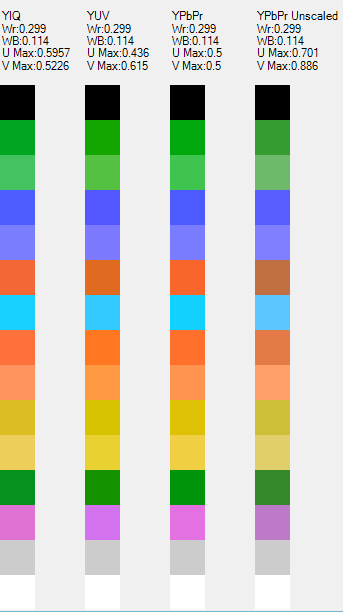
Can someone give me a reality check on this? I've generated a bunch of swatches based on the various component schemes out there (using the TMS9929 raw values) to visualise the difference.
They all seem VERY similar.
Note, have forced values to be within 0% & 100% - i.e. trimmed all under/overflow. That colour #9 is def. wrong in the VDP datasheet.
They all seem VERY similar.
Note, have forced values to be within 0% & 100% - i.e. trimmed all under/overflow. That colour #9 is def. wrong in the VDP datasheet.
SC-3000H, SC-3000H, Amiga 500. Hobbyist electronics and programming.
- natshaw
- Posts: 69
- Joined: Sat Feb 16, 2013 9:44 pm
Re: TMS9929 (Sega etc.) display direct to modern TV!
![]() by honestbob on Mon Sep 30, 2013 11:26 pm
by honestbob on Mon Sep 30, 2013 11:26 pm
Ok, I think I've picked up enough of my notes to rejoin the conversation. I've gone around in circles on a lot of this myself, and I'm still not 100% on whether all my assumptions are correct, and which bits are really relevant to this particular application.
I'm not sure if we are arguing the same point here, but mathematically I think the Y / B-Y' / R-Y' to Y'UV to Y'PbPr conversion is a simple scaling operation as U = (B-Y') * 0.492 and V = (B-Y') * 0.877. And Pb = (B-Y') * 0.564 and Pr = (R-Y') * 0.713
It all comes back to that identity equation of
Y' = 0.299R' + 0.587G' + 0.114B'
That defines a gamma corrected luma function based on the characteristics of the red, green, and blue phosphors that were common back in the early days of PAL and NTSC, and that appears to be what all of these SDTV colour spaces are based on. (HDTV has a slightly different colour space).
From that you can derive
B-Y' = -0.299R' - 0.587G' + 0.886B'
R-Y' = 0.701R' - 0.587G' - 0.114B'
Y'UV is just a scaled version of that where U is the B-Y' colour difference but scaled to a maximum of +/- 0.436. So U = B-Y' * 0.436 / 0.886 = B-Y' * 0.492
Similarly V is the R-Y' colour difference but scaled to a maximum of +/- 0.615. So V = R-Y' * 0.615 / 0.701 = R-Y' * 0.877
In other words, Y / B-Y' / R-Y', Y'UV, and Y'PbPr are equivalent and interchangeable provided you scale the Blue and Red colour difference channels by the appropriate scale factor for the output television system that you are trying to interface to.
So all you should need is a simple resistor / trimpot based voltage divider to transform between those three colour difference representations.
The only part of that I'm not sure is that the above calculations are all based on gamma corrected values. And I can't quite get my head around how relevant that is to the interchangeability of those colour spaces.
Y'IQ is a different matter because I and Q are not a direct scalar of B-Y' and R-Y'. The good news there is that I don't think Y'IQ is relevant for our purposes as it looks like it is more directly related to certain NTSC implementations.
But provided the target for consumer TVs is either Y'PbPr or Y'UV then I think those transformation issues are a side argument. The more interesting question is whether the target for consumer TVs is a different colour space that you cannot use a simple scaling transformation to shift to. If that is the case, then your assertion that you need complex circuitry to properly correct the colour balance is effectively correct.
But what we really want to know is why the TVs display a different colour set to what we are hoping for.
I don't actually think it is related to the exact colour space transformations. I think it could be as simple as that consumer televisions don't conform very closely to broadcast standards. I suspect that if you fed an appropriately scaled signal into a calibrated broadcast quality TV monitor that supports 288p video, then we could get something very close to the correct black, white, and colour levels we expect, and it once you get it right it should work the same on all broadcast quality TVs. But that isn't what I've observed with consumer TVs and monitors. They all treat the input slightly differently. And depending on the TV's brightness, contrast, colour saturation, and sharpness settings you will get further transformations applied to the incoming signal. And the situation gets complicated further still as soon as you move away from an analog CRT screen and the display then starts to digitize the incoming signal and map it to a digital colour space and interpolate it to fit on screen.
Yes, dammit. I know exactly what you mean about the white levels. Ummm... this bit is kind of hard to explain in text form. We'll have to catch up again some time to swap notes when life settles back down a bit
The first thing we are assuming when complaining that we should get a pure white due to the zero colour difference is that your TV can correctly detect the 'zero' voltage level of the incoming B-Y and R-Y signals. By 'zero' voltage I mean the voltage level where B-Y = 0 and R-Y = 0. This is not 0v. And it is not (necessarily) the same as the blanking level or Vblack on the Y channel.
My last breadboard design tried to make that easier for the TV by using the built in sync tip clamp of the THS7314 on the Y channel input, then using a LM1881 video sync seperator, a NOT gate, a CD4066B analog switch, and a diode to generate a keyed clamp that would allow me to set the 'zero' point of the B-Y and R-Y channels to an arbitrary voltage. So I was outputting a 1v p-p Y channel signal, with a B-Y and R-Y signal scaled significantly below the 700mV p-p with the 'zero' level centered half way between the black level voltage and the white level peak. This is a single supply system, so all voltages are positive voltages.
Then from memory (this was several weeks ago), I tried looking at the system just in black and white by zeroing out the amplitude of the B-Y and R-Y signals, but still leaving the 'zero' level offset in there. And I could never quite get a perfect white doing that. I could only get a perfect white by completely disconnecting the B-Y and R-Y signals. So that says that the TV's definition of the 'zero' level was different from mine. And the TV was obviously doing something like a keyed clamp itself because I could shift the zero voltage level of the B-Y and R-Y signals up and down quite a bit without really affecting the picture.
But the flip side of that is the TV is also struggling with my black level as black is significantly brighter on my current component breadboard design than a side-by-side comparison with the original composite output.
It is also hard to pin down which part of the system is causing a given colour balance issue because your experience will likely vary a bit on a different TV, and it may also vary depending on your TV's brightness, contrast, and saturation settings.
So... the perfect solution still remains frustratingly elusive I suspect there is no perfect out of the box solution for consumer grade TVs, but I still think there is a good solution here that will work for a lot of people if we can just improve it a bit more.
natshaw wrote:Essentially, the dodgy colour issue is not easily solvable, as the conversion from YUV to YPbPr is non-linear, as the colour weightings are different. To do it 100% correctly would require mathematical conversion from YUV to RGB, and then to YPbPr.
I'm not sure if we are arguing the same point here, but mathematically I think the Y / B-Y' / R-Y' to Y'UV to Y'PbPr conversion is a simple scaling operation as U = (B-Y') * 0.492 and V = (B-Y') * 0.877. And Pb = (B-Y') * 0.564 and Pr = (R-Y') * 0.713
It all comes back to that identity equation of
Y' = 0.299R' + 0.587G' + 0.114B'
That defines a gamma corrected luma function based on the characteristics of the red, green, and blue phosphors that were common back in the early days of PAL and NTSC, and that appears to be what all of these SDTV colour spaces are based on. (HDTV has a slightly different colour space).
From that you can derive
B-Y' = -0.299R' - 0.587G' + 0.886B'
R-Y' = 0.701R' - 0.587G' - 0.114B'
Y'UV is just a scaled version of that where U is the B-Y' colour difference but scaled to a maximum of +/- 0.436. So U = B-Y' * 0.436 / 0.886 = B-Y' * 0.492
Similarly V is the R-Y' colour difference but scaled to a maximum of +/- 0.615. So V = R-Y' * 0.615 / 0.701 = R-Y' * 0.877
In other words, Y / B-Y' / R-Y', Y'UV, and Y'PbPr are equivalent and interchangeable provided you scale the Blue and Red colour difference channels by the appropriate scale factor for the output television system that you are trying to interface to.
So all you should need is a simple resistor / trimpot based voltage divider to transform between those three colour difference representations.
The only part of that I'm not sure is that the above calculations are all based on gamma corrected values. And I can't quite get my head around how relevant that is to the interchangeability of those colour spaces.
Y'IQ is a different matter because I and Q are not a direct scalar of B-Y' and R-Y'. The good news there is that I don't think Y'IQ is relevant for our purposes as it looks like it is more directly related to certain NTSC implementations.
But provided the target for consumer TVs is either Y'PbPr or Y'UV then I think those transformation issues are a side argument. The more interesting question is whether the target for consumer TVs is a different colour space that you cannot use a simple scaling transformation to shift to. If that is the case, then your assertion that you need complex circuitry to properly correct the colour balance is effectively correct.
But what we really want to know is why the TVs display a different colour set to what we are hoping for.
I don't actually think it is related to the exact colour space transformations. I think it could be as simple as that consumer televisions don't conform very closely to broadcast standards. I suspect that if you fed an appropriately scaled signal into a calibrated broadcast quality TV monitor that supports 288p video, then we could get something very close to the correct black, white, and colour levels we expect, and it once you get it right it should work the same on all broadcast quality TVs. But that isn't what I've observed with consumer TVs and monitors. They all treat the input slightly differently. And depending on the TV's brightness, contrast, colour saturation, and sharpness settings you will get further transformations applied to the incoming signal. And the situation gets complicated further still as soon as you move away from an analog CRT screen and the display then starts to digitize the incoming signal and map it to a digital colour space and interpolate it to fit on screen.
natshaw wrote:Interestingly, without any conversion, the YUV levels of the Sega are not OVERLY different from the YPbPr levels that your TV expects. Slightly weird shading of course, and that's what we've seen. What I find odd, is that the whites are not right, when in theory they should be the same. Perhaps attenuation at the trimpots is to blame? If the colour differences are at zero (relative to the zero level of the Y) then TV image should have no colour component at all.
Yes, dammit. I know exactly what you mean about the white levels. Ummm... this bit is kind of hard to explain in text form. We'll have to catch up again some time to swap notes when life settles back down a bit
The first thing we are assuming when complaining that we should get a pure white due to the zero colour difference is that your TV can correctly detect the 'zero' voltage level of the incoming B-Y and R-Y signals. By 'zero' voltage I mean the voltage level where B-Y = 0 and R-Y = 0. This is not 0v. And it is not (necessarily) the same as the blanking level or Vblack on the Y channel.
My last breadboard design tried to make that easier for the TV by using the built in sync tip clamp of the THS7314 on the Y channel input, then using a LM1881 video sync seperator, a NOT gate, a CD4066B analog switch, and a diode to generate a keyed clamp that would allow me to set the 'zero' point of the B-Y and R-Y channels to an arbitrary voltage. So I was outputting a 1v p-p Y channel signal, with a B-Y and R-Y signal scaled significantly below the 700mV p-p with the 'zero' level centered half way between the black level voltage and the white level peak. This is a single supply system, so all voltages are positive voltages.
Then from memory (this was several weeks ago), I tried looking at the system just in black and white by zeroing out the amplitude of the B-Y and R-Y signals, but still leaving the 'zero' level offset in there. And I could never quite get a perfect white doing that. I could only get a perfect white by completely disconnecting the B-Y and R-Y signals. So that says that the TV's definition of the 'zero' level was different from mine. And the TV was obviously doing something like a keyed clamp itself because I could shift the zero voltage level of the B-Y and R-Y signals up and down quite a bit without really affecting the picture.
But the flip side of that is the TV is also struggling with my black level as black is significantly brighter on my current component breadboard design than a side-by-side comparison with the original composite output.
It is also hard to pin down which part of the system is causing a given colour balance issue because your experience will likely vary a bit on a different TV, and it may also vary depending on your TV's brightness, contrast, and saturation settings.
So... the perfect solution still remains frustratingly elusive
- honestbob
- Posts: 92
- Joined: Thu Jan 05, 2012 8:21 am
- Location: New Zealand
Re: TMS9929 (Sega etc.) display direct to modern TV!
![]() by honestbob on Tue Oct 01, 2013 6:03 am
by honestbob on Tue Oct 01, 2013 6:03 am
natshaw wrote:Can someone give me a reality check on this? I've generated a bunch of swatches based on the various component schemes out there (using the TMS9929 raw values) to visualise the difference.
They all seem VERY similar.
Note, have forced values to be within 0% & 100% - i.e. trimmed all under/overflow. That colour #9 is def. wrong in the VDP datasheet.
Nice job. I tried something similar before in reverse a page or two back where I took the Sega SC-3000 palette from MESS, assumed that was a 'correct' or at least close to correct RGB representation of the TMS9929A palette, then tried to map the voltages listed in the TMS9929A datasheet to those RGB values. That matched almost exactly (apart from colour #9) if you assume that the voltages in the TMS9929A datasheet are unscaled B-Y' / R-Y' values (ie. where B-Y' has a +/- range of 0.886 and R-Y' has a +/- range of 0.701).
However
The key point there is that the person who selected those colours for MESS isn't necessarily correct
For instance, Wikipedia suggests a slightly different palette for the MSX. But then again, that table refers to the TMS9918 which may actually have a slightly different colour balance.
MSX Colour Palette
http://en.wikipedia.org/wiki/List_of_8- ... SX_systems
This bit is useful reading for how to read the YPbPr values in the tables in that article.
http://en.wikipedia.org/wiki/List_of_8- ... deo_colors
And I also like this bit as it refers to the difference in the actual perceived colours when viewed through an RF modulator.
Also, when seen on TV devices through an RF modulator, the perception of these colors may be not corresponding with the original YPbPr ones (most noticeable with NTSC TV color system, due to its YIQ color space plane is not one-to-one compatible with YPbPr and YUV).
So... the other side of this argument is that the exact colour mapping isn't necessarily that relevant. The original Texas Instrument engineers chose some fairly arbitrary values to display on the primitive CRTs of the time, and which would give you colors that can be saturated out quite a lot by the colour adjustment controls on those displays. ie. you kind of expect the end user to boost up the saturation to some sort of personal preference level so that the displayed colours don't look exactly like the 'true' RGB representation anyway.
But you notice some colour imperfections more than others. Getting a good black and a good white are important. The tricky issue in practice is maintaining those whilst still being able to saturate the other colours and keep them all in the right range.
Cheers
- honestbob
- Posts: 92
- Joined: Thu Jan 05, 2012 8:21 am
- Location: New Zealand
Re: TMS9929 (Sega etc.) display direct to modern TV!
![]() by natshaw on Wed Oct 02, 2013 12:03 am
by natshaw on Wed Oct 02, 2013 12:03 am
All that tip-sync stuff went over my head, but I agree, if Y black-to-white range (i.e. excl. sync) is 700 mV then chroma levels at black + 350 mV should give a monochrome image. Unless we're missing something about gamma, but adjusting amplitude of Y should allow us to get a mono image. Hmmm....time to stop theorising, I need to go dig out those opamps and get my signals connected to TV!
Side issue - I disagree about YIQ, I reckon it's the same as the others, just slightly different chroma scales again.
Side issue - I disagree about YIQ, I reckon it's the same as the others, just slightly different chroma scales again.
SC-3000H, SC-3000H, Amiga 500. Hobbyist electronics and programming.
- natshaw
- Posts: 69
- Joined: Sat Feb 16, 2013 9:44 pm
Re: TMS9929 (Sega etc.) display direct to modern TV!
![]() by honestbob on Tue Oct 15, 2013 1:26 pm
by honestbob on Tue Oct 15, 2013 1:26 pm
Hi All
Just some interesting background reading for thinking about what it is your TV / monitor controls actually do, and in practical terms what things like gamma, greyscale, colour, colour temperature etc. mean with examples of what different settings do to a test picture.
Toms Hardware: Display Calibration 201: The Science Behind Tuning Your Monitor
http://www.tomshardware.com/reviews/cal ... ,3615.html
It also has some interesting insights like that your Brightness control actually sets the black level and the Contrast control actually sets the white level. eg.
So... not directly applicable, but good background reading to help understand the problem of getting a well balanced image on a TV / monitor. Just be aware that the TMS9929A is probably designed more for Rec 601 (SDTV) than Rec 709 (HDTV), so there is a slight difference in the colour space. And obviously you can't reproduce all of those test patterns with an arbitrary 16 colour palette.
Cheers
Just some interesting background reading for thinking about what it is your TV / monitor controls actually do, and in practical terms what things like gamma, greyscale, colour, colour temperature etc. mean with examples of what different settings do to a test picture.
Toms Hardware: Display Calibration 201: The Science Behind Tuning Your Monitor
http://www.tomshardware.com/reviews/cal ... ,3615.html
It also has some interesting insights like that your Brightness control actually sets the black level and the Contrast control actually sets the white level. eg.
What we’re talking about are black and white levels, or, as they’re more commonly known, brightness and contrast.
At some point in history, a not-so-clever television engineer decided that the controls affecting dynamic range should be called brightness and contrast rather than black level and white level. This has created confusion as to what these adjustments are actually for. It’s actually quite simple, though. Brightness is black level and contrast is white level.
Now, what are we doing when we change those controls? Black level/brightness refers to the minimum level of light a display will produce. White level refers to the maximum level of light. Obviously, by minimizing black and maximizing white, you'll achieve the highest contrast ratio and the greatest dynamic range possible for a given display. The trick is to set the levels properly, while retaining all of the image's detail.
So... not directly applicable, but good background reading to help understand the problem of getting a well balanced image on a TV / monitor. Just be aware that the TMS9929A is probably designed more for Rec 601 (SDTV) than Rec 709 (HDTV), so there is a slight difference in the colour space. And obviously you can't reproduce all of those test patterns with an arbitrary 16 colour palette.
Cheers
- honestbob
- Posts: 92
- Joined: Thu Jan 05, 2012 8:21 am
- Location: New Zealand
Voltage levels on Luminance?
![]() by natshaw on Sat Dec 28, 2013 10:02 pm
by natshaw on Sat Dec 28, 2013 10:02 pm
I made a current amplifier circuit (BC547 and 2 resistors), but my TV still behaves as with the unamplified signal (trouble locking on to picture initially, image quite dim).
So, is 1x voltage gain enough?
Honestbob, have you tried?
So, is 1x voltage gain enough?
Honestbob, have you tried?
SC-3000H, SC-3000H, Amiga 500. Hobbyist electronics and programming.
- natshaw
- Posts: 69
- Joined: Sat Feb 16, 2013 9:44 pm
Re: TMS9929 (Sega etc.) display direct to modern TV!
![]() by natshaw on Sun Feb 21, 2016 8:01 pm
by natshaw on Sun Feb 21, 2016 8:01 pm
Just ordered 2 spare TMS9929 VDP chips from e-Bay. Will resurrect this project soonish! Will add some video buffering to prevent further blowing-up of VDP.
SC-3000H, SC-3000H, Amiga 500. Hobbyist electronics and programming.
- natshaw
- Posts: 69
- Joined: Sat Feb 16, 2013 9:44 pm
Re: TMS9929 (Sega etc.) display direct to modern TV!
![]() by natshaw on Sun Feb 21, 2016 9:19 pm
by natshaw on Sun Feb 21, 2016 9:19 pm
VDP Programmer's guide. Covers both the PAL & NTSC versions, and the later 91xx replacements. 9929A vs 9129 difference seems to be one pin that is CPUCLK vs GROMCLK, haven't looked into that yet.
http://map.grauw.nl/resources/video/ti-vdp-programmers-guide.pdf
http://map.grauw.nl/resources/video/ti-vdp-programmers-guide.pdf
SC-3000H, SC-3000H, Amiga 500. Hobbyist electronics and programming.
- natshaw
- Posts: 69
- Joined: Sat Feb 16, 2013 9:44 pm
Re: TMS9929 (Sega etc.) display direct to modern TV!
![]() by natshaw on Wed Jan 04, 2017 2:54 pm
by natshaw on Wed Jan 04, 2017 2:54 pm
Not component, but composite. Good picture from Samsung 830MP. Usual Sega low colour saturation boosted on monitor.
- Attachments
-
- IMG_5304.JPG (657.43 KiB) Viewed 2152465 times
SC-3000H, SC-3000H, Amiga 500. Hobbyist electronics and programming.
- natshaw
- Posts: 69
- Joined: Sat Feb 16, 2013 9:44 pm
Re: TMS9929 (Sega etc.) display direct to modern TV!
![]() by honestbob on Fri Jan 20, 2017 10:35 am
by honestbob on Fri Jan 20, 2017 10:35 am
Hi All
Thanks to a recent hint from Natshaw, I think I've finally got the result I have been looking for. Good black and white level and good saturation on all colours for component Y / Pb / Pr (see test pattern below)
Natshaw found this hackaday project which had essentially solved the problem with MSX output from a TMS9929A to RGB / Component:
https://hackaday.io/project/13056-tms99 ... nt-adapter
I was missing two crucial insights when I last looked at this back in 2013:
1. The TV samples EACH of Y / Pb / Pr INDEPENDENTLY during the back porch ON EVERY SINGLE LINE to set the Vblack and Vnocolor voltage levels.
2. The TMS9929A has a positive pulse on the R-Y and a negative pulse on the B-Y during the back porch (this is where colour burst is inserted in composite video, but there should not be anything there in a YPbPr component signal). This screws up the sampling of the Vnocolor level for Pb and Pr when you plug those signals into your TV component inputs.
(IMPORTANT - the TMS9928 does NOT have these burst pulses on R-Y and B-Y. I don't think the TMS9928 was ever used in any Sega products, but if you have something using a TMS9928, then you don't have to worry about pulses on R-Y and B-Y)
The problem always appeared to be that the TV was struggling to get a consistent reading on the black level and the relative levels of R-Y and B-Y. I tried to fix that with a keyed clamp on the R-Y and B-Y channels to set a consistent DC offset to match the Y channel. But of course that wasn't the problem main problem - those pulses the TMS9929A inserts during the back porch were still there.
That hackaday project published a schematic which I worked through until I understood it (if you are working on a similar mod then you should definitely look at that for reference). Some of it was actually quite similar to my keyed clamp circuit - it certainly used most of the same parts. So I reworked my THS7316 based circuit to incorporate a sample / hold and it works pretty well.
Anyway - photos!
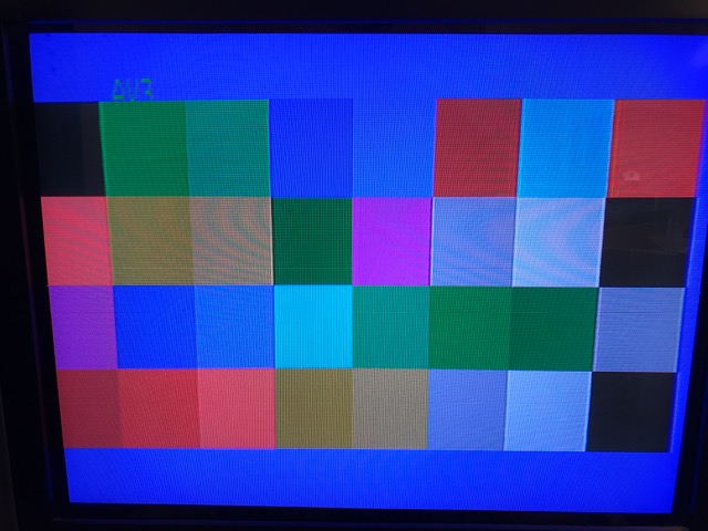
Test Pattern. It looks better than this live. My iPhone always struggles to get a decent picture of a CRT. In particular the black is very black. The white is ever so slightly greyish still. Blues and reds very blue and red. Greens and yellows a little muted, but nice. As discussed previously games are almost unwatchable if all of your colours are super bright as it is too hard on your eyes, so this is actually a pretty nice balance.
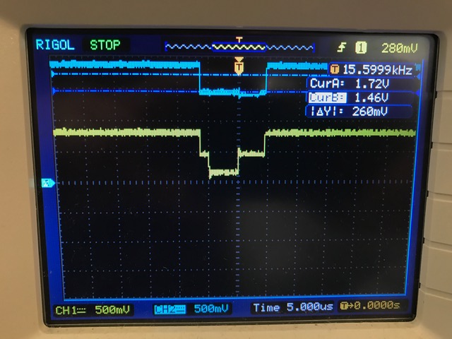
Scope Output (blue line) of 2Pr output from THS7316 on a line that is just showing Medium Red (color 8 in the TMS9929A palette - max R-Y voltage output). You can see the positive pulse during the back porch. Boo! (Yellow line is 2Y output)
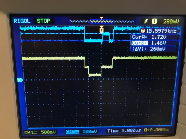
Scope Output (blue line) of 2Pr output with the sampled Vnocolor plugged in during the back porch on a line that is just showing Medium Red (color 8 in the TMS9929A palette - max R-Y voltage output). There is slight voltage dip (around 6mV), and a reduction in noise during the sample / hold playback. But pretty darn close. No more pulse. Yay! (Yellow line is 2Y output)
And finally, the schematic of the circuit used for this.
Note - I wouldn't try to build this one as there are aspects I'm not that happy with and I want to refine it further. I may actually end up dumping the THS7316 and just using an opamp solution. Pros and cons with both approaches I certainly started with the THS7316 because I thought it would simplify aspects of the circuit design. It does a bit, but not as much as I'd hoped.
http://sc3000-multicart.com/images/comp ... dWorks.pdf
EDIT 10 Feb 2017 - look at the next page of this thread for a simpler op-amp based circuit without the THS7314/7316 if you want to build one. It is still useful to understand how this one works though, especially the sample-hold part of the circuit and how removing those back porch pulses on R-Y and B-Y fixes the Vnocolor level
I will make a second post describing the important parts of how it works.
Cheers
Thanks to a recent hint from Natshaw, I think I've finally got the result I have been looking for. Good black and white level and good saturation on all colours for component Y / Pb / Pr (see test pattern below)
Natshaw found this hackaday project which had essentially solved the problem with MSX output from a TMS9929A to RGB / Component:
https://hackaday.io/project/13056-tms99 ... nt-adapter
I was missing two crucial insights when I last looked at this back in 2013:
1. The TV samples EACH of Y / Pb / Pr INDEPENDENTLY during the back porch ON EVERY SINGLE LINE to set the Vblack and Vnocolor voltage levels.
2. The TMS9929A has a positive pulse on the R-Y and a negative pulse on the B-Y during the back porch (this is where colour burst is inserted in composite video, but there should not be anything there in a YPbPr component signal). This screws up the sampling of the Vnocolor level for Pb and Pr when you plug those signals into your TV component inputs.
(IMPORTANT - the TMS9928 does NOT have these burst pulses on R-Y and B-Y. I don't think the TMS9928 was ever used in any Sega products, but if you have something using a TMS9928, then you don't have to worry about pulses on R-Y and B-Y)
The problem always appeared to be that the TV was struggling to get a consistent reading on the black level and the relative levels of R-Y and B-Y. I tried to fix that with a keyed clamp on the R-Y and B-Y channels to set a consistent DC offset to match the Y channel. But of course that wasn't the problem main problem - those pulses the TMS9929A inserts during the back porch were still there.
That hackaday project published a schematic which I worked through until I understood it (if you are working on a similar mod then you should definitely look at that for reference). Some of it was actually quite similar to my keyed clamp circuit - it certainly used most of the same parts. So I reworked my THS7316 based circuit to incorporate a sample / hold and it works pretty well.
Anyway - photos!
Test Pattern. It looks better than this live. My iPhone always struggles to get a decent picture of a CRT. In particular the black is very black. The white is ever so slightly greyish still. Blues and reds very blue and red. Greens and yellows a little muted, but nice. As discussed previously games are almost unwatchable if all of your colours are super bright as it is too hard on your eyes, so this is actually a pretty nice balance.
Scope Output (blue line) of 2Pr output from THS7316 on a line that is just showing Medium Red (color 8 in the TMS9929A palette - max R-Y voltage output). You can see the positive pulse during the back porch. Boo! (Yellow line is 2Y output)
Scope Output (blue line) of 2Pr output with the sampled Vnocolor plugged in during the back porch on a line that is just showing Medium Red (color 8 in the TMS9929A palette - max R-Y voltage output). There is slight voltage dip (around 6mV), and a reduction in noise during the sample / hold playback. But pretty darn close. No more pulse. Yay! (Yellow line is 2Y output)
And finally, the schematic of the circuit used for this.
Note - I wouldn't try to build this one as there are aspects I'm not that happy with and I want to refine it further. I may actually end up dumping the THS7316 and just using an opamp solution. Pros and cons with both approaches
http://sc3000-multicart.com/images/comp ... dWorks.pdf
EDIT 10 Feb 2017 - look at the next page of this thread for a simpler op-amp based circuit without the THS7314/7316 if you want to build one. It is still useful to understand how this one works though, especially the sample-hold part of the circuit and how removing those back porch pulses on R-Y and B-Y fixes the Vnocolor level
I will make a second post describing the important parts of how it works.
Cheers
Last edited by honestbob on Fri Feb 10, 2017 5:37 am, edited 3 times in total.
- honestbob
- Posts: 92
- Joined: Thu Jan 05, 2012 8:21 am
- Location: New Zealand
Re: TMS9929 (Sega etc.) display direct to modern TV!
![]() by honestbob on Fri Jan 20, 2017 12:47 pm
by honestbob on Fri Jan 20, 2017 12:47 pm
Hi All
Schematic
http://sc3000-multicart.com/images/comp ... dWorks.pdf
As promised, an explanation of the main parts of this circuit. I want to rework it, so I wouldn't build this one directly. But the main point of this thread is to leave a paper trail for anyone else playing around with it. So here is how it works.
EDIT 10 Feb 2017 - look at the next page of this thread for a simpler op-amp based circuit without the THS7314/7316 if you want to build one. It is still useful to understand how this one works though, especially the sample-hold part of the circuit and how removing those back porch pulses on R-Y and B-Y fixes the Vnocolor level
BTW - read the explanation on that hackaday page about the TMS9929A pulses on the back porch on R-Y and B-Y channels. You can see them in the graphic there.
The short explanation of how the circuit gets rid of the pulses on R-Y and B-Y is that it uses a LM1881 sync seperator to determine when the sync interval is and the burst / back porch interval. During the sync interval, it samples and stores the value of Vnocolor for the R-Y and B-Y channels in a sample and hold circuit, then during the burst interval it plays back the stored Vnocolor instead of the R-Y and B-Y signals (thereby eliminating the pulses).
(IMPORTANT - the TMS9928 does NOT have these burst pulses on R-Y and B-Y. I don't think the TMS9928 was ever used in any Sega products, but if you have something using a TMS9928, then you don't have to worry about pulses on R-Y and B-Y)
1. Video signals to the TV should be 1v peak to peak for the Y channel. ie. 0.3v for the sync pulse, 0.7v from Vblack to Vwhite
2. The TMS9929A on the SC-3000 outputs Y with a 1.44v range from Vsync to Vwhite (instead of 1v range), and a DC offset of 1.92v (Vsync is 1.92v)
That gives a 1v range from Vblack to Vwhite, with Vsync 0.44v
The R-Y and B-Y channels are output on the same voltage scale as Y
Here are some useful voltage measurements for reference that I took back in 2013:
Vwhite = 3.34v
Vblack = 2.36v (so approx 1v from Vblack to Vwhite)
Vsync = 1.92v (so Y channel is approx 1.44v peak to peak)
Vno_color = 2.80v (B-Y) or 2.84v (R-Y)
Vb-y 100% = 3.32v
Vr-y 0% = 2.38v
Those correspond almost exactly to the voltage offsets from the TMS9929A manual, as discussed back in 2013.
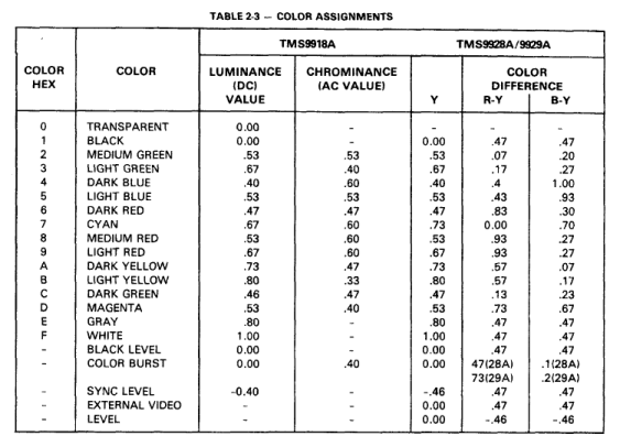
So for instance from that table you can see that Vnocolor is Vblack + 0.47v = 2.36v + 0.47v = 2.83v (closely matches observed 2.80v to 2.84v), and for the dark blue colour B-Y = Vblack + 1.00v = 3.36v (closely matches observed 3.32v), and for the cyan colour R-Y = Vblack + 0.00v = 2.36v (closely matches observed 2.38v).
3. So based on the above, we know that Y / R-Y / B-Y must be scaled by 1 / 1.44 = 0.694 at the TV outputs to get them into the 1v p-p range for Y / Pb / Pr. Call it a factor of 0.7.
We have a voltage divider circuit on the Y input from the TMS9929A. Note that R1 + R2 = 470ohms as per the TMS9929A datasheet.
Then R2 = 0.7 * 470ohms = 329ohms approx = 330ohms and R1 = 140ohms for an approx 0.7 multiplier on Y
4. In addition, Pb and Pr have further scaling required. See earlier discussion in this thread from June 2013.
For YPbPr you need to scale B-Y by 0.564 to get Pb and R-Y by 0.713 to get Pr.
So B-Y is scaled by 0.564 * 0.7 = 0.395
So R6 = 0.395 * 470ohms = 186ohms approx = 190ohms
R5 = 284ohms approx = 280ohms
I used a 500ohm trimpot and did my best to adjust the voltage split as I didn't have the correct resistors around.
So R-Y is scaled by 0.713 * 0.7 = 0.4991
Call it 0.5 - close enough
So R3 = R4 = 235ohms. I think I used two 240 ohm resistors instead.
4. THS7316 - dedicated 3 channel HD-TV video amplifier with inbuilt filters and some other magic
Big brother of THS7314 which was designed for SDTV use. I thought the output noise was slightly lower on the THS7316 so I ran with that.
These are cool chips. They have a fixed 2x gain, so that when you run the output into a 75ohm resistor the voltage drops back to 1x gain at the TV input (because the TV inputs are terminated to ground through a 75ohm resistor too). The chips also allow you the choice of AC coupling or DC coupling both the inputs and outputs. There is a sync tip clamp built in if you AC couple the input, and you can also use a large pullup resistor (R7 and R8 - in the order of 2Mohm to 3Mohm) to give AC coupled output a DC offset again. You can also drive up to two lines off each output. Various built in filters too.
And if it wasn't for those bloody burst pulses on B-Y and R-Y, it would make for a very simple component video mod. Actually, even with the pulses intact you can get reasonable output.
5. Scaled Y / R-Y / B-Y inputs from TMS9929A are AC coupled to the THS7316
The incoming signals from the TMS9929A have a significant DC offset. Even if I scaled back to 1v p-p (Vwhite 2.35v), I was very close to the clipping limit on the outputs of the THS7316 after the 2x gain and level shift. So I ran with AC coupling. And that is brilliant for the Y channel as it has a built in tip sync clamp and level shift to keep your sync pulse sitting at around 290Mv on the output.
R-Y and B-Y signals do not have a sync pulse so you need to give them a new DC offset. The THS7316 will do that for you if you put a large pull up resistor (R7 and R8 - in the order of 2Mohm to 3Mohm) to give AC coupled output a DC offset again.
6. LM1881 sync seperator
This is a very cool little chip. You feed it the Y signal, and it outputs !CSYNC (drops low during the sync interval) and !BURST (drops low during the color burst interval of the back porch.
This is how we know when to sample Vnocolor during sync and when to play it back during burst (back porch)
7. CD4066B Quad Bi-lateral switch
This IC has switches in it that open and close on a control signal. So when it is NOT the burst interval, we pass 2xPb and 2xPr to the output. And when it IS the sync interval, we pass 2xPb and 2xPr to the sample / hold parts of the circuit to save Vnocolor for playback during the burst interval to replace those sync pulses on R-Y and B-Y
(This bit is borrowed heavily from that Hackaday project mentioned earlier)
8. Sample / Hold Circuit
When it is the sync interval, the 4066 switch passes the 2xPb and 2xPr output from the THS7316 into a sample / hold circuit formed by a 0.01uF capacitor and a op-amp. I used AD828 as I had those around, but a lower grade op-amp would do here.
(Note the !CSYNC output from the LM1881 is passed through a 74LS04 NOT gate to give CYNC. The Hackaday project used a spare 4066 gate for this purpose. I tried that out of interest by low voltage was over 1 volt and I didn't get the cleanest transition on it, so I went for LS04 NOT gate).
This works because during CSYNC, the 4066 closes the switch and 2xPb or 2xPr feeds into the op-amp and charges the capacitor. Because it is during sync, the TMS9929A is outputting Vnocolor for R-Y and B-Y
When CSYNC ends, the 4066 closes the switch. The capacitor continues to output Vnocolor to the positive input of the op-amp. Together they hold the voltage.
Just after CSYNC ends, !BURST goes low (because it is now back porch / burst), and that closes the feed from the 2xPb and 2xPr. The pull up resistors from the op-amp outputs then 'play back' the Vnocolor that we sampled during CSYNC to the output.
(Note - we need a final op-amp just before the output for the pullup resistor approach to work.)
9. Outputs are DC coupled through a 75ohm resistor
That drops the 2x gain down to 1x gain at the output. The THS7316 can run with either AC coupled or DC coupled outputs. But because I have carefully put reasonable DC offsets on everything now I will run with that. Plus I read a design note somewhere that it is common design practice to AC couple your inputs and DC couple your outputs. But whatever you do, you always assume that the next stage will play a similar game to reestablish a good DC offset.
That's most of the important stuff I'm glad I made all the earlier notes as I couldn't remember how any of this stuff when worked natshaw called me a couple of weeks back about that hackaday project. Hopefully it is useful to someone else someday.
Cheers
Schematic
http://sc3000-multicart.com/images/comp ... dWorks.pdf
As promised, an explanation of the main parts of this circuit. I want to rework it, so I wouldn't build this one directly. But the main point of this thread is to leave a paper trail for anyone else playing around with it. So here is how it works.
EDIT 10 Feb 2017 - look at the next page of this thread for a simpler op-amp based circuit without the THS7314/7316 if you want to build one. It is still useful to understand how this one works though, especially the sample-hold part of the circuit and how removing those back porch pulses on R-Y and B-Y fixes the Vnocolor level
BTW - read the explanation on that hackaday page about the TMS9929A pulses on the back porch on R-Y and B-Y channels. You can see them in the graphic there.
The short explanation of how the circuit gets rid of the pulses on R-Y and B-Y is that it uses a LM1881 sync seperator to determine when the sync interval is and the burst / back porch interval. During the sync interval, it samples and stores the value of Vnocolor for the R-Y and B-Y channels in a sample and hold circuit, then during the burst interval it plays back the stored Vnocolor instead of the R-Y and B-Y signals (thereby eliminating the pulses).
(IMPORTANT - the TMS9928 does NOT have these burst pulses on R-Y and B-Y. I don't think the TMS9928 was ever used in any Sega products, but if you have something using a TMS9928, then you don't have to worry about pulses on R-Y and B-Y)
1. Video signals to the TV should be 1v peak to peak for the Y channel. ie. 0.3v for the sync pulse, 0.7v from Vblack to Vwhite
2. The TMS9929A on the SC-3000 outputs Y with a 1.44v range from Vsync to Vwhite (instead of 1v range), and a DC offset of 1.92v (Vsync is 1.92v)
That gives a 1v range from Vblack to Vwhite, with Vsync 0.44v
The R-Y and B-Y channels are output on the same voltage scale as Y
Here are some useful voltage measurements for reference that I took back in 2013:
Vwhite = 3.34v
Vblack = 2.36v (so approx 1v from Vblack to Vwhite)
Vsync = 1.92v (so Y channel is approx 1.44v peak to peak)
Vno_color = 2.80v (B-Y) or 2.84v (R-Y)
Vb-y 100% = 3.32v
Vr-y 0% = 2.38v
Those correspond almost exactly to the voltage offsets from the TMS9929A manual, as discussed back in 2013.
So for instance from that table you can see that Vnocolor is Vblack + 0.47v = 2.36v + 0.47v = 2.83v (closely matches observed 2.80v to 2.84v), and for the dark blue colour B-Y = Vblack + 1.00v = 3.36v (closely matches observed 3.32v), and for the cyan colour R-Y = Vblack + 0.00v = 2.36v (closely matches observed 2.38v).
3. So based on the above, we know that Y / R-Y / B-Y must be scaled by 1 / 1.44 = 0.694 at the TV outputs to get them into the 1v p-p range for Y / Pb / Pr. Call it a factor of 0.7.
We have a voltage divider circuit on the Y input from the TMS9929A. Note that R1 + R2 = 470ohms as per the TMS9929A datasheet.
Then R2 = 0.7 * 470ohms = 329ohms approx = 330ohms and R1 = 140ohms for an approx 0.7 multiplier on Y
4. In addition, Pb and Pr have further scaling required. See earlier discussion in this thread from June 2013.
For YPbPr you need to scale B-Y by 0.564 to get Pb and R-Y by 0.713 to get Pr.
So B-Y is scaled by 0.564 * 0.7 = 0.395
So R6 = 0.395 * 470ohms = 186ohms approx = 190ohms
R5 = 284ohms approx = 280ohms
I used a 500ohm trimpot and did my best to adjust the voltage split as I didn't have the correct resistors around.
So R-Y is scaled by 0.713 * 0.7 = 0.4991
Call it 0.5 - close enough
So R3 = R4 = 235ohms. I think I used two 240 ohm resistors instead.
4. THS7316 - dedicated 3 channel HD-TV video amplifier with inbuilt filters and some other magic
Big brother of THS7314 which was designed for SDTV use. I thought the output noise was slightly lower on the THS7316 so I ran with that.
These are cool chips. They have a fixed 2x gain, so that when you run the output into a 75ohm resistor the voltage drops back to 1x gain at the TV input (because the TV inputs are terminated to ground through a 75ohm resistor too). The chips also allow you the choice of AC coupling or DC coupling both the inputs and outputs. There is a sync tip clamp built in if you AC couple the input, and you can also use a large pullup resistor (R7 and R8 - in the order of 2Mohm to 3Mohm) to give AC coupled output a DC offset again. You can also drive up to two lines off each output. Various built in filters too.
And if it wasn't for those bloody burst pulses on B-Y and R-Y, it would make for a very simple component video mod. Actually, even with the pulses intact you can get reasonable output.
5. Scaled Y / R-Y / B-Y inputs from TMS9929A are AC coupled to the THS7316
The incoming signals from the TMS9929A have a significant DC offset. Even if I scaled back to 1v p-p (Vwhite 2.35v), I was very close to the clipping limit on the outputs of the THS7316 after the 2x gain and level shift. So I ran with AC coupling. And that is brilliant for the Y channel as it has a built in tip sync clamp and level shift to keep your sync pulse sitting at around 290Mv on the output.
R-Y and B-Y signals do not have a sync pulse so you need to give them a new DC offset. The THS7316 will do that for you if you put a large pull up resistor (R7 and R8 - in the order of 2Mohm to 3Mohm) to give AC coupled output a DC offset again.
6. LM1881 sync seperator
This is a very cool little chip. You feed it the Y signal, and it outputs !CSYNC (drops low during the sync interval) and !BURST (drops low during the color burst interval of the back porch.
This is how we know when to sample Vnocolor during sync and when to play it back during burst (back porch)
7. CD4066B Quad Bi-lateral switch
This IC has switches in it that open and close on a control signal. So when it is NOT the burst interval, we pass 2xPb and 2xPr to the output. And when it IS the sync interval, we pass 2xPb and 2xPr to the sample / hold parts of the circuit to save Vnocolor for playback during the burst interval to replace those sync pulses on R-Y and B-Y
(This bit is borrowed heavily from that Hackaday project mentioned earlier)
8. Sample / Hold Circuit
When it is the sync interval, the 4066 switch passes the 2xPb and 2xPr output from the THS7316 into a sample / hold circuit formed by a 0.01uF capacitor and a op-amp. I used AD828 as I had those around, but a lower grade op-amp would do here.
(Note the !CSYNC output from the LM1881 is passed through a 74LS04 NOT gate to give CYNC. The Hackaday project used a spare 4066 gate for this purpose. I tried that out of interest by low voltage was over 1 volt and I didn't get the cleanest transition on it, so I went for LS04 NOT gate).
This works because during CSYNC, the 4066 closes the switch and 2xPb or 2xPr feeds into the op-amp and charges the capacitor. Because it is during sync, the TMS9929A is outputting Vnocolor for R-Y and B-Y
When CSYNC ends, the 4066 closes the switch. The capacitor continues to output Vnocolor to the positive input of the op-amp. Together they hold the voltage.
Just after CSYNC ends, !BURST goes low (because it is now back porch / burst), and that closes the feed from the 2xPb and 2xPr. The pull up resistors from the op-amp outputs then 'play back' the Vnocolor that we sampled during CSYNC to the output.
(Note - we need a final op-amp just before the output for the pullup resistor approach to work.)
9. Outputs are DC coupled through a 75ohm resistor
That drops the 2x gain down to 1x gain at the output. The THS7316 can run with either AC coupled or DC coupled outputs. But because I have carefully put reasonable DC offsets on everything now I will run with that. Plus I read a design note somewhere that it is common design practice to AC couple your inputs and DC couple your outputs. But whatever you do, you always assume that the next stage will play a similar game to reestablish a good DC offset.
That's most of the important stuff
Cheers
Last edited by honestbob on Fri Feb 10, 2017 5:37 am, edited 2 times in total.
- honestbob
- Posts: 92
- Joined: Thu Jan 05, 2012 8:21 am
- Location: New Zealand
Return to Repair and Restoration
Who is online
Users browsing this forum: Google [Bot] and 86 guests