Disassembling a Compaq SLT/286 Portable Computer
Introduction
Recently I had to crack open my Compaq SLT/286 to modify the Dallas battery IC deep within. I found getting to the main board was an involved process. I figured other people also might have a reason to do this so I documented the disassembly process in photos. Hopefully, this narrative and its accompanying photos will be of use to someone.
Disassembly
First thing you will need is a special torx screwdriver. All the screws are of this nature. There are lots of screws and it would pay to work through the disassembly very methodically making sure you know which screw goes where for the subsequent reassembly.
With the power unplugged and the battery removed, the first task is to remove the six screws in the plastic cover on the back of the machine (Fig 1) and then pry the cover off. The cover is clipped on by snap clips so even when the screws are out it still takes some effort to remove it. Take it easy as you don't want to break the plastic lugs.
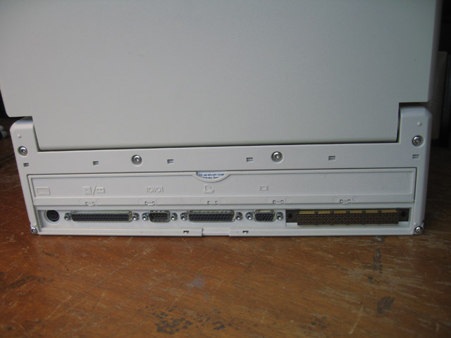
Fig 1. Plastic cover at the back of the machine
After the cover is off, you can remove the plastic shoulders on either side covering the video cables (Fig 2). These pieces of plastic just pull off.

Figure 2. Plastic shoulder covering the video cable
There is no need to unscrew the screen, but you will need to remove the keyboard plug (just pull to unplug then twist to clear) (Fig 3) and unclip the earth wire next to it (Fig 4), underneath the right shoulder (looking from the front).

Figure 3. Keyboard removal. Note the earth wire next to it

Figure 4. Earth wire for the screen. This needs to be detached
After that is done, it's time to slide the inner metal casing from inside the outer, plastic one (Fig 5).

Figure 5. Inner metal casing ready to be pulled out from the exterior shell
This is done by pulling it out from the rear. The case can be difficult to move. It may be wedged in tight. Pushing at the back of the battery compartment can help. At first, don't pull it out too far. There is still the main video cable to unplug but you can't get to it until you pull the inner case out a centimeter or two.
Figure 6 shows the main video cable, which you should be able to see once the inner case has moved out a little. Unscrew the clamp, then tug the plug out of its socket using the handy paper handle.

Figure 6. Main video cable (to be unplugged)
After removing the cable the whole inner case can be gently removed from the shell.

Figure 7. Sliding the inner case away from the outer shell
Your SLT/286 should now look like Figure 8.

Figure 8. The naked SLT/286
There are now four components occupying the top and back of the case which need to be removed to progress. The box with the drives' indicator lights (mid-front), the hard and floppy disk drives and the power supply unit at the back.
To remove the light box, undo the four screws and gently pull upwards. The box is attached with a card edge and should detach with gentle force (Fig 9).

Figure 9. Drive indicator assembly seen detached from the main board
Next unplug the hard disk cable and power plug at the back of the hard drive, remove all screws holding the hard drive casing down (I think there are eight) and remove the drive in its entirety. Figure 10 shows the computer with the hard drive removed.

Figure 10. Hard drive removed from top of inner case
Do the same for the floppy disk. You should now be looking at something that resembles Figure 11.

Figure 11. Floppy drive removed. PSU is the oblong unit along the back
Time to remove the power supply you can see at the back. This is held in by three screws. Remove these and also gently remove the power cable plug from its socket on the main board. While you're at it, remove the floppy disk cable.
The top tray is now virtually naked and should look like Figure 12.

Figure 12. A naked top casing
The top casing can now be removed. From memory, you only need to remove the screw in the centre right, and two side screws on the left. After this is done you can lift away the top of the casing as shown in Figure 13. Lift away and move it forward, being careful not to snag the hard disk power cable.

Figure 13. Removing the top casing
The main board now stands revealed (Fig 14).

Figure 14. Main board revealed at last
Complete disassembly requires the removal of the bottom casing though. First remove the interface board in the lower right. This is plugged into the main board by a card arrangement and secured by just one screw. Remove this screw then pull gently but firmly directly upwards. The board will come free revealing the ICs underneath (Fig 15).

Figure 15. The completely revealed main board
To remove the main board completely, remove any remaining screws in the board, then turn your attention to the connectors at the back. Unscrew the bolts associated with each one of these.

Figure 16. The bolts associated with the connectors
After this is done, you should be able to simply slip the main board out (Fig 17).

Figure 17, The main board. Free at last!
That's all there is to it. Assembly is simply the reverse. I found the biggest hassle during re-assembly was the video cable, which has to be shepherded into place when pushing the inner casing back into the shell and re-clipping the plastic cover on the back.
Best of luck with your attempt!
Tez
6th December, 2009
| Tweet |