Errors in the schematics in the NEC 8201a Service Manual
 Introduction
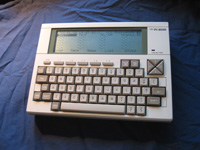
During a recent fix, I used the NEC PC-8201A Service Manual w/Schematics, downloadable from web8201.com. I discovered a couple of errors in the circuit diagrams in this manual which I feel are worth documenting.
My initial thought was to correct the errors using Photoshop and Adobe Acrobat and make the document available a revised PDF. However, the original scan would have been of a REAL document (errors and all) so rather than muddy authentic sources with amended e-documents I decided just to list those errors here. Besides, there may be more errors than just those listed.
Hopefully, this information will save others hours of frustration.
Error 1 - The ROM circuit diagram
Looking at the ROM circuit diagram (Appendix D), Both A8 and A11 are labeled as being on pin 23? I was sure A8 should be labeled as pin 25. Using the circuit diagram I looked for where the A8 and A11 lines went. They went to a gate IC just before the CPU. With power off I found the signal from pin 25 of the ROM to the A8 input pin on the gate IC (U14) showed complete continuity (0 ohms). The A11 line on pin 23 of the ROM also showed 0 ohms between it and the A11 input pin on this gate IC.
Conclusion: A8 should be labeled as coming off pin 25 of the ROM, not pin 23.
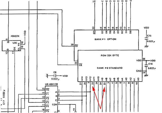
Figure 1. Incorrect pin labeling of the A8 line from ROM
Error 2 - The RAM circuit diagram
In the RAM schematic, pin 25 from the RAM IC is labeled as A10. However, a closer look shows that another pin 25 listed, which is labeled /WR!!
As pin 23 was the only number missing in the schematic I figured the RAM pin associated with A10 should have been pin 23. I checked the A10 pin on the same IC as above (U14) and sure enough the circuit measured 0 ohms between that and pin 23 on the RAM.
Conclusion: A10 comes off pin 23 of the RAM IC, not pin 25.
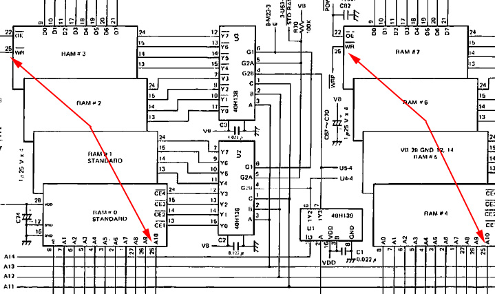
Figure 2. Incorrect pin labeling of the A10 data line from the RAM ICs
Others have suggested there are more errors in these schematics. Use them with care.
If I find any more I'll update this entry.
Tez
22nd February, 2010
| Tweet |