Repairing and Restoring an IBM XT
 Introduction
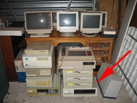
The Wellington haul provided some vintage computer goodies.
Foremost amongst these was a genuine IBM XT! The XT wasn't a model I'd been actively chasing but it does have historic significance so it is certainly worth owning.
Grubby and neglected-looking, it showed no sign of life when the big red switch was thrown.
A clear candidate for restoration and repair!
PSU or something downstream?
To the uninitiated no sign of life with the XT would seem to point to a power supply problem. However, that is not necessarily the case with Intel-type PCs. In case of a short circuit somewhere, the PSU's have special circuitry to check if it's safe to flow the juice to the motherboard. If a short circuit appears to exist, the PSU simply won't fire.
Luckily I had a couple of ways to determine if the fault was in the PSU or elsewhere. I had an old XT clone motherboard in the spare parts pile. Furthermore, I knew this board was ok, as I'd tested it before. This clone board had the same sort of power connectors as the real XT. If the PSU fired up when plugged into this board and the voltages were right, it would show the PSU at least was ok.
I plugged the PSU to the clone board and flipped the switch. The fan whirred up to speed. The PSU was alive! I took voltage readings on the board. The readings were fine.
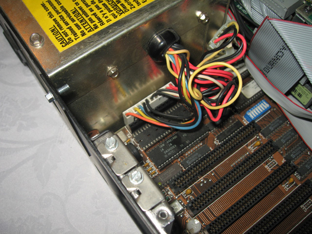
Figure 1. Power connector on the XT motherboard
The evidence strongly pointed then to a short-circuit downstream of the PSU. To gather further clues, I checked the continuity between the +ve voltage pins and ground on the unplugged board itself. They should show some resistance. Sure enough the -12 voltage pin (the pin the blue wire connects to - see figure 1) showed a short straight through to ground. I did the same check on the clone board. Here the test showed clear resistance. Definitely a short circuit on the IBM XT motherboard!
Finding the short
The fault could have been on the motherboard, or the cards attached to it. I removed all cards and tested the shorted line again. No change. The reading was still at 0 ohms!
Time for some serious fault finding. I disassembled the machine and removed the motherboard.
What could cause a short like this? Tantalum capacitors were a major suspect. A similar problem on a disk drive controller card had stopped my IBM AT from firing. Certainly it was worth exploring this hypothesis. But which capacitor? There were dozens on the motherboard. I decided to start with those nearest the PSU connector. I put an ohm meter across the first one. Bingo! A closed circuit with no resistance! These caps should have high resistance across them and this one was showing zero. I knew that was not definitive though. These caps are often connected in parallel and it could be a short in some other part of the circuit rather than the cap itself. To determine if it really WAS the cap, I'd have to measure it when off the circuit. It was a good start though.
There was another tantalum next to it. I measured that one too. Also zero resistance. Now I had two suspects.
Before going any further I decided to check these suspect caps out. I had to remove them from the circuit to get a definitive reading, but once I did that I could prove they were faulty or eliminate them as suspects. I managed to do this on the first one by extracting one leg from the motherboard. I then measured across the cap itself. Very high resistance! Ok, it wasn't that one.
The next cap had three legs rather than two and was harder to get out. I've noticed as you move up through the years during the 1980's tracks get closer and closer together and the soldering gets finer and finer on circuit boards. A reflection of the automation introduced in constructing these things I guess. Anyway, I had to be very careful I didn't damage anything when desoldering. I had to extract the whole thing to test. Eventually it was out safely. Testing across all three legs this time though showed a very different result to the first one. Almost no resistance at all!! This must be the shorted capacitor!

Figure 2. Tantalum capacitors extracted for testing
The fix
I tucked the protruding leg of the good capacitor back in and resoldered. What to use as a replacement for the other one though? I'd never seen a tantalum cap with THREE legs before?? Could I replace it with a standard two-legged one? Again, the Web came to the rescue. I found some old pages from the Vintage Computer Forums where this very topic was discussed. It was OK to use a two legged replacement PROVIDING the +ve lead goes in the middle hole.
I had just the component at hand and soon had it soldered in. I dropped a video board into a slot in the bare motherboard, hooked up a screen, added the PSU to the mix and switched on. The PSU roared into life! The memory check ticked away on the screen until it reached 640k. Excellent!! Then I got the expected errors as the system looked for the other parts of the machine that were suppose to be plugged in (and weren't).
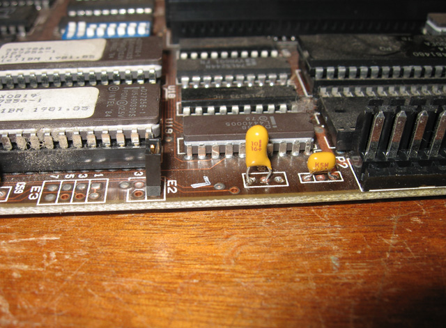
Figure 3. Capacitor replacement snugly in place
Great. The motherboard was now working and the memory was fine. Time to plug everything back in and see what other issues were lurking.
Drive issues
The system came with a multifunction card. I decided to leave this out during testing as it's best to minimising any complicating factors until I had a bootable minimum system. After reassembing and adding the floppy and hard disk controllers, I booted once more. Lights blinked, hard drives rumbled quietly. Then a message appeared saying the system was unable to boot. This was completely expected. Hard drives that have been sitting unused for about 20 years don't take kindly to a rude awakening. It's also possible this disk had issues anyway, which was the trigger for the whole system being replaced back in the day in the first place.

Figure 4. IBM-XT partially reassembled for the drive tests
Were the floppies ok? I decided to be systematic about the check out and focus on the floppies first. I unplugged the hard drive, gave drive A: a clean with a cleaning disk and tried to boot from a floppy disk. No worries! Before I knew it, the A:> prompt was smiling at me from the screen.
How about the B: drive. Hmm...not so promising. In fact, the machine didn't acknowledge its existence at all! As far as it was concerned, A: and B: were the same physical drive!?
Time to recap. The XT passed all its POST checks fine. It recognised the hard drive but couldn't boot from it. However it didn't recognise drive B.
Hard Drive. Viable or not?
I decided to disconnect the B: drive for the time being and focus on the hard drive. I could list the root directory and load the odd file but mostly the drive presented me with failure-type error messages. I figured I needed to give it a low-level format and take it from there. But how to do this? With my AT this was largely an automatic process facilitated by software kindly given to me. From reading my copy of Scott Mueller's book "Upgrading and Repairing PCS (1st edition)" it seems I had to find a routine that (I hoped) was hidden in the hard disk controller card. There was certainly a BIOS chip (BXD07) in this Data Technology Corp DTC5150CX card. I expected the low-level format routine was in it?
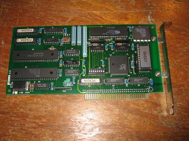
Figure 5. Hard drive controller card
There were dip switches on this card so the first thing to do was to source some docs to see what these switches did. As usual, the Web was my savoiur in these matters. They weren't actually docs, just tables as to various supported configurations. I could kind of make sense of them. It didn't tell me exactly where the low-level format routine was though. As suggested in Mueller's book I tried -g C800:6 from Debug only to be met with a hang preceded with:
1701 (20)
1 Hard Disk
Hmmm.
Looking up the error code sheet this was a hard disk parity failure. Sounded serious.
At this stage I wondered if the drive was actually toast. In other words, the low level format utility detected the drive but it was in such bad condition it couldn't go any further? If this was the case, there was little point in continuing. I decided to get an opinion on the Vintage Computer Forums. The general consensus of opinion there was to persist. I just may not have got the configurations right.
The disappearing hard drive!
Persist I did. But weird things were happening. I now found the machine couldn't even recognise the hard drive? It said it was present on boot up but when I tried to access C: I was told there wasn't one?? It had gone the same way as drive B:!
I mentioned this strange symptom on the forum and one member, Floppies_only, suggested I check the cable for loose pins. Give that man a cigar, he was right! A check of the cable revealed damage.
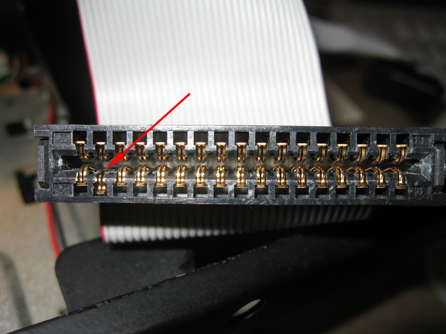
Figure 6. Damaged pin at the hard disk end of the drive cable
A quick rummage around in the parts box sourced a new cable and I was back in business.
A myriad of options
Now that the machine recognised it always had a hard drive I started to look again for the elusive low-level format utility. I tried -g c800:5 this time and bingo! I got the following message..
Hard Disk Formatting Utility V3.0
"This program will erase all data on the specified hard disk.
Enter a hard disk number (1 to 8 ) or press "q" to quit:"
Numbers 1 to 8? What the hell were those? Eventually, and after much discussion on the VCF, we figured they were the NUMBER of drives attached to the controller (why 8 when there were only connectors for two, heaven knows!). The tables for the controller dip switches showed they were in the right position for the Segate ST-225 20MB, half-height drive I had (i.e. 20Mb, 4 heads, 612 cylinders). After sorting all these parameters out and making sense of the confusing tables, I was ready to go. I booted up the formatting utility and selected "1".
After a few minutes my drive had a successful low-level format! It was then a matter of booting with PC-DOS 3.2, FDISK'ing and the FORMATting the hard drive. This process passed with no hiccups. I now had a bootable 20MB hard drive!
Drive B reappears
While I was checking configurations for the hard disk format I discovered why the unit disowned it's second floppy drive. The motherboard dip switches were set for only one! I set them for two floppy drives, and hey presto! I had two!
Graphics and multifunction card
Now I had the basics working I checked out the graphics card and the multifunction card that came with the machine. The graphics card was a Paradise duel select CAG/Mono hercules compatible card with printer port. Whoo hoo! This is just what I wanted. I had CGA on my IBM PC and EGA on my AT. It was only fitting to have hercules graphics on my XT. I had a hercules graphics XT clone at home for a number of years. This is how I remember the 8088 machines!
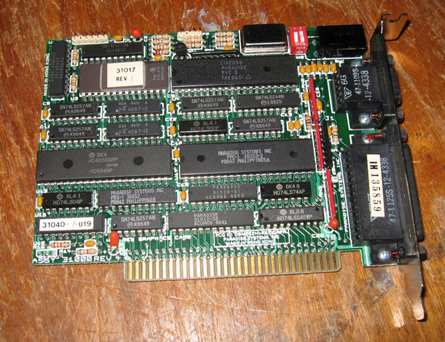
Figure 7. Paradise graphics card
The multifunction card was the usual clock/calendar, two printer and two serial ports affair. I managed to find the necessary dip switch specs for that too. The lithium button clock battery was flat of course. I disabled the clock until I could get around to buying a new battery for it.
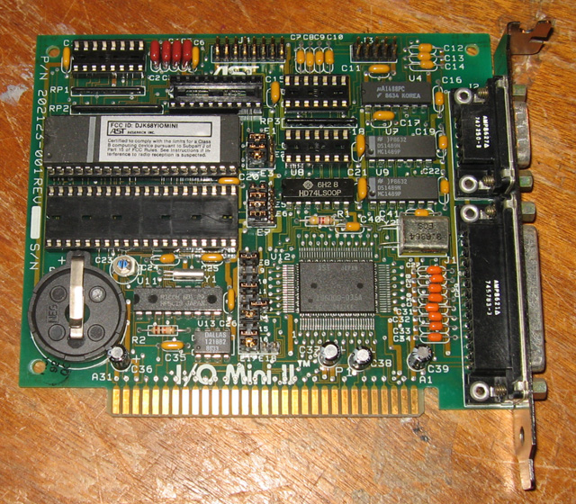
Figure 8. Multifunction card
Cleaning, reassembling and testing
Cleaning can be a chore but the results are well worth it. This XT was grubby in all aspects...the keyboard, the unit and the Philips mono monitor that came with it. Before reassembly I gave them all a good clean. Laborious and not at all interesting but boy, does it lift the appearance.
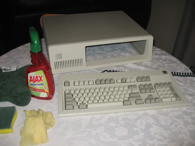
Figure 9. Cleaning the case and keyboard
After the cleaning was done, it was time to put the cover on, bolt down all the parts and give the machine a thorough test workout. For this I used a program called CHECKIT. Everything came up fine. including the hard disk. Well..almost fine. For some reason Checkit couldn't read the disks in drive A: to begin its floppy drive test? This was odd, as in normal use I could read and write to that drive just fine? Disks made in A: could be used in B: and vice versa? Maybe the drive was configured in a way that Checkit just didn't like. Anyway, it seemed to be working ok, so I accepted that theory for now.
Here it is! The result of a few nights work. From a dirty and dead hunk of scrap to a handsome and working later model (256/640 board) IBM XT!
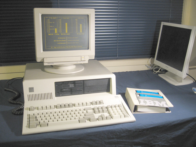
Figure 10. My restored IBM XT
Reflections
This is the first time I'd restored an XT-type machine. It brought home just how complicated things started to get once you had hard disks involved and a variety of non-plug-and-play devices. Dip switch settings ruled and you have to know what you are doing. Mueller's book was a useful reference in this regard.
Along with the XT was bundled a loose monster full-height 30MB Quantum Q540. I was going to use this in place of the ST-225 but in the end I decided it would be more authentic with the latter. This was a later model XT after all (probably 1985), with two 1/2 height floppies and a number of third party cards. A half-height drive would be closer to how it would have been stacked in the day.
Another member of the IBM family to join its PC, AT, PS/2 30-286 and PS/2 70 siblings. Cool!
Tez
5th November, 2010