Repairing two Apple II "Disk II"-modified TEAC Disk Drives
From two working TEACS to zero working TEACS!
The Apple haul contained a number of disk drives. As with all the equipment in that lot, they were dirty and neglected. However, with a bit of TLC, some cleaning and alignment I managed to get four of the six of them working.
Two of the working ones were fancy half-height TEAC drives. These were smooth and quiet and a joy to use. Strangely one stopped working a few months ago. Still having a working drive, I snatched some time one weekend to attempt a diagnosis and repair. I figured I would swap the circuit boards, cables and back planar (a small circuit board on the TEAC used to fool the computer into thinking it was talking to an Apple Disk II drive) and so isolate the problem.
Well, that was the plan. At the end of the night I had TWO non-working TEAC drives!
How did this happen? Alas, standard Apple II disk controllers are not idiot-proof in that it is very easy to plug the drive cable in incorrectly while testing equipment (see photo 1).
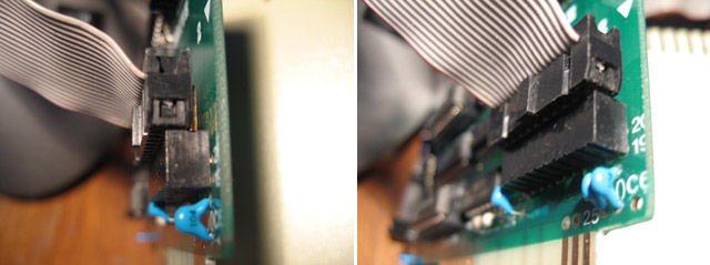
Photo 1. How NOT to plug in an Apple II disk drive
This is exactly what I did to my working drive, zapping something with a 12v surge that it was not designed to take!. At first I thought it might have been a non-working index light but discussion on the Vintage Computer Forums confirmed the plug mistake was the likely cause. Thinking back, I remembered accidentally doing this to the FIRST (non-working) drive before it gave up the ghost. That is probably why it stopped going in the first place!
Skilling up for diagnosis
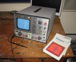 Photo
2. A useful diagnostic tool
Photo
2. A useful diagnostic tool
My usual shotgun method of systematic IC replacement wasn't going to work on this problem. None of the ICs were socketed. This was going to require a more sophisticated approach.
My friend Philip Avery has some skill in electronics. He also owns an oscilloscope and had assisted me with diagnosing a non-working PET and aligning a Kaypro drive using this tool. Knowing I had some repair work ahead of me, Philip offered me use of this diagnostic machine for a few months.
Before attempting the drive repairs I did two things. One was to have a crash-course in how to use an oscilloscope with Philip Avery and the other was to get hold of the book "Electronics for Dummies" and read it through, particularly the section on integrated circuits and how to read circuit diagrams.
 Going
through the book was well worth it. I'd picked up quite a bit of electronics
knowledge from repairing these old beasts, but much of it was fragmented.
I didn't really understand what was going on. After
reading through the book, things just crystallized and I could suddenly
see clearly what digital electronics was about. I finally UNDERSTOOD what
ICs and digital circuits did! Circuit diagrams suddenly started to mean
something to me rather than being indecipherable.
Going
through the book was well worth it. I'd picked up quite a bit of electronics
knowledge from repairing these old beasts, but much of it was fragmented.
I didn't really understand what was going on. After
reading through the book, things just crystallized and I could suddenly
see clearly what digital electronics was about. I finally UNDERSTOOD what
ICs and digital circuits did! Circuit diagrams suddenly started to mean
something to me rather than being indecipherable.
I was starting to "get it".
Diagnosis and repair
Looking at the circuit diagram suggested the 74LS04 Hex inverter would be a good place to start. Philip was also of this opinion, during our oscilloscope training session.
I googled the data sheet for this IC. The data sheet told me exactly what to expect on each pin. I booted the drive, and measured the signals on the pins. Ah ha... Something was suspicious on the very first measurement. Pins 1 and 2 were the input and output of a HEX inverter. This means if the signal is high on the input, it should be low on the output and vice versa. In the test, the signal was high on both!?
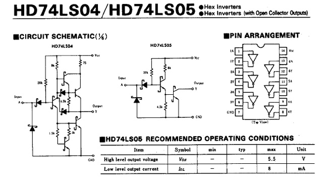
Figure 1. Part of the data sheet on the 74LS04 IC
The IC was faulty!
I tested the other drive, with the same result. Hopefully, this was the IC that bore the brunt of the mis-plug and replacing it would fix the problem? I removed the board and clipped out the IC, leaving the pins in place. I wanted to see if it was indeed this chip before soldering in a new one, so I simply piggybacked a replacement IC over the embedded lugs to test (photo 4).
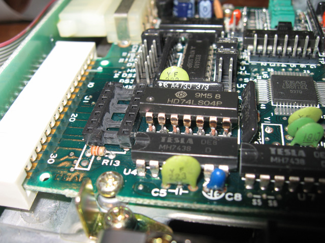
Photo 3. Piggybacking a replacement IC over the old pins
The boot sequence started, and the drive happily loaded up ProDos. YES!!!!
After pausing to savour the moment, I soldered in a new IC, and then proceeded to do the same with the second drive. However....that drive still didn't work. Hmm...
A second problem
The second drive didn't zap the working disk like it did before. It didn't read it though either? I swapped the back planar between the drives to help isolate the problem. The problem moved with the planar! Ah ha..it was on that board somewhere.
There were three ICs on the planar. I checked them all out with the oscilloscope, using spec. sheets found on the web (Figure 2) so I knew what signals to expect. Two seemed fine, but the third IC (a Hex 3-State Buffer) was showing a voltage of 1v on 3 and 5 output pins which, given that 1,2 and 4 were low, should have been indicating low (i.e. 0v) .

Figure 2. Hex 3-state buffer IC
Checking the same IC on the working planar showed these output pins as 0v. I also checked the other two ICs on the working planar, and they matched exactly the values on the non-working one. Of the ICs on the board, only the 74LS367A showed a difference. One volt should have been enough to pull the signal low, however it was suspicious enough for me to replace the IC.
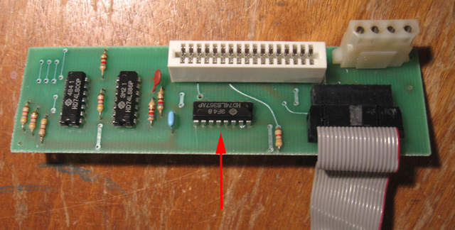
Photo 4. The dubious IC on the back planar
This was duly done. I booted up the drive and.....it loaded ProDos perfectly. YES!!!
All fixed
So...I now have my beautiful TEAC drives back in action again.
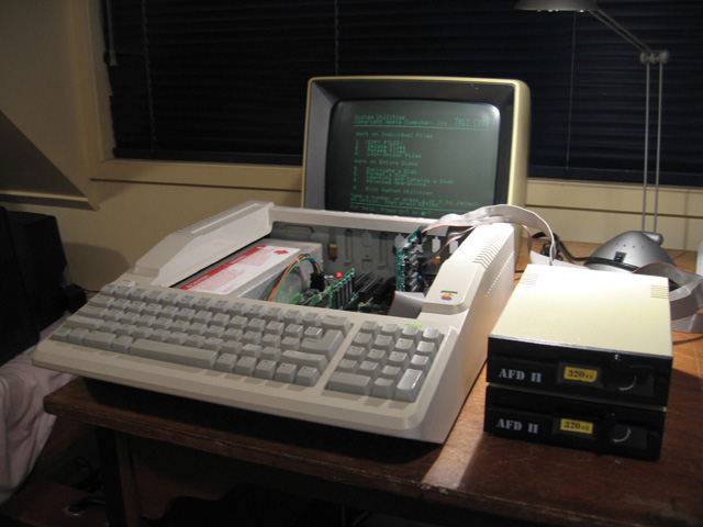
Photo 5. The TEAC drives live again
The value in this repair wasn't just the drives though. I couldn't take the easy way out with this one. There were no POST messages like there were in the IBM-PC repair and I couldn't just swap the ICs out as I had in the other Apple jobs. I had to understand what was going on.
So I learnt a lot. Using IC data sheets and understanding (now) what goes on in logic chips enabled me to predict what values I should see on the pins. Circuit diagrams are finally starting to make sense to me.
If you are like me, with no training in electronics but you want to keep old machines going, take heart. You CAN do it. What you need is support (provided to me from those on the Vintage Computer Forums - thanks guys!), some test equipment (thanks Philip), the motivation to learn, patience and the willingness to give it a go!
It's a lot of fun and very rewarding.
Tez
23rd March, 2009