TRS-80 Model 1 RS-232 - The puzzling case of the burnt-out baud rate generator
Introduction
Ever since I threw out my home-made System 80 RS-232 some years ago (Duh!) I've always wanted one back. Both my System 80 and TRS-80 Model 1 use NEWDOS 80/V2 single-density disk formats and hence it's not easy (i.e. impossible) to read/write these disks in a 5.25 inch drive in a PC. Although my semi-virtual diskette negates this somewhat, it's a hassle to create a disk image just for a single file. Transferring via RS-232 is much easier.
Naturally then, I was very pleased when I managed to get hold of a card (figure 1) thanks to a hardware swap with a TRS-80 enthusiast. Problem is, although this card may have worked in a previous life, it didn't work for me! Here is the story of the fault and the fix.
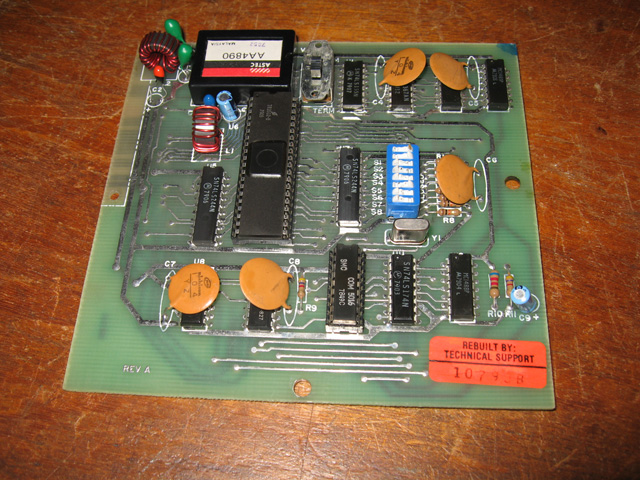
Figure 1. Newly received RS-232 card. Not all was well though (read on)
Installing the board
Installation wasn't difficult although it wasn't obvious how this bit of kit fits into the RS-232 expansion unit and cables itself to the outside world. The Web wasn't much help either. However the seller (or should I say swapper) kindly provided a couple of copied manuals for installation and use of the card, and for technical service. As it turned out, these documents were crucial for making progress.
Soon the card was installed and ready for testing
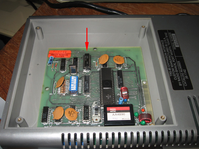
Figure 2. The RS-232 card in situ. Arrow shows the baud rate generator IC
The symptom
The board didn't work. I tried it first with the TERM program designed to test it with loopback. Then I tried Omniterm. I tried it connected to the PC with hyperterminal. Then my NEC 8201a using the Telecom program. Not a peep. Hmm. To investigate further I ran the card through Howe Software's handy System Diagnostic program. The Framing and Connector test passed but the Transmit Data Test and Loopback Test failed. OK. Something was wrong.
Nothing untoward was obvious from a careful look. However, before probing around with a voltmeter and scope I laid a finger on each chip to see if they were overly hot or stone cold. This can indicate failure. Ouch! The COM5016 baud rate generator was so hot you could fry (miniature) eggs on it! Ok, so here was something suspicious. An IC that hot is not normal! I wondered if it was an internal short so I tested connectivity between all the pins. Nope, there was always some resistance.
Time to look at some documents.
Research
While I was sure the COM5016 was faulty, I didn't want to simply replace it. The problem might be wider than just the IC. It wasn't shorted, yet it got very hot. Why? I figured I needed to know more about this IC and the circuitry that fed it.
As usual the web provided a datasheet on COM5016. I also had the circuit diagram from the Model 1 RS-232 manual. Less relevant but also useful was technical information I had on the Model III/4 RS-232 interface.
Looking at these three documents I noticed some odd things. The Model 1 circuit diagram indicated a -5V input on pin 10 (figure 3).
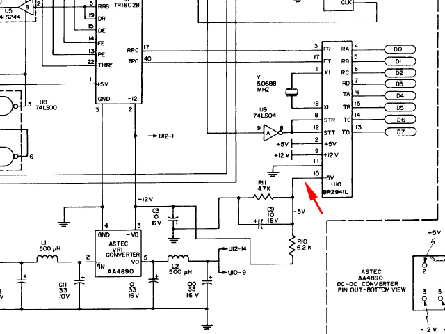
Figure 3. - 5 volts indicated on pin 10 of the baud rate generator
The COM 5016 datasheet though, specified this pin as a "1/4 crystal/clock frequency reference output"? The Model 4 RS-232 docs went even further. They specified COM5016 as the baud rate generator to use but said that pin 10 was unconnected. In fact the document even warned against connecting pin 10 to anything, saying the pin was used for internal reference only?
So why was a COM5016 being used here? Was it the right IC? Contrary to the Model 4 docs, the Model 1 RS-232 information specified a BR2941 IC not a COM5016. I searched and eventually found the datasheet on BR2941. Uh ha, yes, this chip WAS suppose to have -5V on pin 10. The BR2941 was cited in its datasheet as being a low-power version of BR1941, the latter being compatible with COM5016 and also the COM8116.
Ok, surely this was the reason. This was the wrong IC. It was getting fed -5v where it shouldn't have been.
Conflicting information
The collector who provided me with the RS-232 had four others. Just as a final check, I wanted to know which baud generators were used in those ones. I figured they would be all BR2941s. Imagine my surprise when all the boards showed BR1941 or COM8116 as the baud rate generators. What??? But surely the docs say those chips are unsuitable for the circuitry! Mind you, one did have a heat sink attached.
My source was apologetic about the card not working and was more than happy to provide a replacement IC. I wanted to get to the root of this mystery though. I didn't want the replacement to go the same way as the original.
So, just to summarise:
- My RS-232 card wasn't working and the COM5016 baud rate generator chip was running extremely hot
- The model 1 RS-232 circuit diagram showed -5 V on pin 10 of the baud rate generator, which it specified should be a BR2941.
- The docs for COM5016 and it's compatibles BR1941 and COM8116 said pin 10 was a reference pin and should not be connected.
- However, of four other cards seen, one was using a COM8116, two were using BR1941s and the forth IC was covered with a heat sink?!
What was going on here??
Mystery solved
Sometimes you just need to ask for help from the community. Accordingly, I posted a note on the Vintage Computer Forums. TRS-80 aficionado Ian Mavric answered and thankfully shed light on the problem.
It seems there are TWO versions of the Model 1 board. The early version has the -5 volt line to pin 10 of the baud rate generator and has to use BR2941. However the later version has the capacitors and resistors that supply this voltage removed (although the tracks are still in place) meaning these cards CAN use BR1941, COM5016 or COM8116. A card comparison can be seen in figure 4.
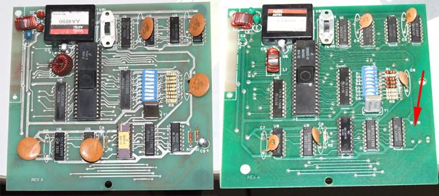
Figure 4. The two versions side by side. Note the missing components in the later board on the right.(Photo by Ian Mavric)
My source's remaining four boards were all of this later type, which explained the absence of BR2941 chips in his batch.
What's confusing is that the missing circuitry is THE ONLY THING that distinguishes these two variants. They even both hold the sub-label "Revision A"??
I wondered if COM5016 could actually stand up temporarily to -5v on pin 10? This would explain why a previous owner might have got by with COM5016 for a while not realising there was anything untoward. TRS-80 hardware guru Knut Roll-Lund answered this in a question I put to the Yahoo TRS-80 group. Knut felt that it was possible for the IC to be challenged in this way for a little while, but it would certainly stress it!
Checking the card with a replacement baud rate generator
I now had a solution to my problem. The answer was to either get hold of a BR2941 chip or disable the -5V circuitry and use a COM5016/BR1941 or COM8116 replacement. The latter chips seemed much move available than the former, so getting rid of the -5V seemed the best option. Had using the wrong IC done any other damage though? I didn't want to acquire a replacement IC only to find there was another issue lurking in the circuitry.
My collection came to the rescue. I'd remembered my Kaypro II had had baud rate generator issues. I checked and sure enough the machine had an 8116 I could use for a test (figure 5).
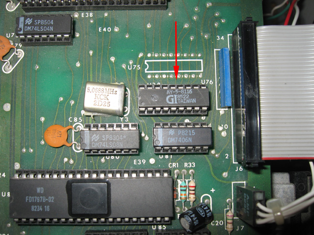
Figure 5. The 8116 Kaypro II baud generator used for keyboard input
Before testing the RS-232 card, I dropped the COM5016 into my Kaypro II. As I suspected, this chip was toast. The Kaypro keyboard was completely unresponsive!
Now for the RS-232. The 8116 was added to the card with pin 10 carefully bent out, so there was no contact with -5 Volts whilst in the socket (Figure 6)
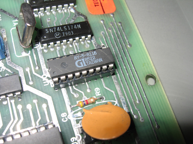
Figure 6. A safe way to use a 8116 IC in this RS-232 board
Test results
Perfect! Not only did the card pass all the tests with the diagnostic software but the TRS-80 Model 1 could now communicate with the PC. (figure 7). The 8116 also remained cool.
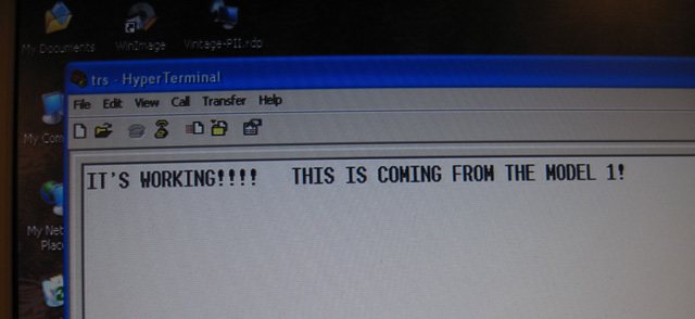
Figure 7. Text in the PC's hyperterminal which originated at the TRS-80 Model 1 keyboard
Conclusion
I'd found the following things...
- There are two versions of the Model 1 RS-232 card. The early one has a -5V circuit requiring the much rarer BR2941 baud rate generator IC to be used. The later card is missing the components which feed -5 volts to pin 10, therefore it is safe to use the more common BR1941/COM5016 or COM8116 ICs.
- An early type board can be converted into a later type board by simply removing the two resistors and a capacitor which feeds -5 volts to pin 10 of the baud rate generator.
- COM5015 or compatible IC's don't like -5v on pin 10, and this voltage will overheat the IC leading to failure. To use one in an early version of the RS-232 card requires conversion as in (2), cutting the track to pin 10 or bending out the pin of the IC so it does not enter the socket.
Reflections
This problem would have been difficult to solve without IC datasheets, circuit diagrams and people (like Ian Mavric) who just "knew" of the two card versions . I'm not sure how the COM5016 came to be in an early RS-232 card but I suspect the original one failed and the owner, perhaps lacking a circuit diagram or datasheet, felt this more available IC would do the job. It probably did for a little while.
It is interesting to speculate why there were two versions of the card. My feeling is that Tandy initially designed the board to use the BR2941 as it is a low-power version of the BR1941 and draws less current. This may have been a consideration in the early EIs where adding the board may have already stretched a fully committed EI PSU. Then maybe it was discovered that (particularly perhaps in newer versions of the EI) power issues were not critical. In that case why not use the standard version of the chip? It probably cost less, was a lot more common than the low-power version and they could cut down the components required as they didn't need to supply -5v for it. Who knows really for sure.
 \
\
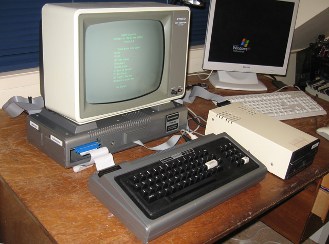
Figure 8. Getting closer to a full TRS-80 Model 1. Still need to get a badged screen and drive.
Anyway, my RS-232 problem is solved and I learned something along the way!
Tez
29th October, 2011