NEC PC-8201a RS-232 Fault - Diagnosis and Fix (Part 2)
Introduction
A little while ago, my friend Philip Avery and I got together to solve an issue with my NEC PC-8201a. The RS-232 port had stopped working. After a few hours at the workbench we came up with a workaround for the problem, but were never entirely convinced we’d cracked the case (see part 1 of this article).
A few days later, upon further examination, we found what seemed to be the root cause. Yesterday I replaced a part which confirmed that diagnosis and solved the problem. This article is about that final fix!
Recap
As a workaround to the problem, we had jumpered two multiplex ICs, U21 and U19, essentially bypassing port selection in the NEC PC-8201a and hardwiring in the RS-232 as the active serial port. However, this was not a fix. There was a possibility that both chips were faulty but the odds or two developing faults at the same time seemed highly unlikely! We decided to continue the investigation…with Philip working remotely via email this time.
Going deeper
There were a couple of input lines U21 and U19 shared in common. These were the SEL A and SEL B lines (See Figure 1). These needed to be LO (0 volts) for the RS-232 to be selected.
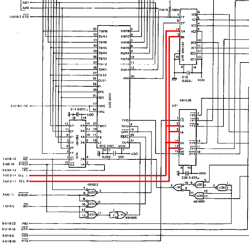
Figure 1. The SELECT lines for U21 and U19
When we measured these lines with a scope, they did seem to be at zero volts. However we felt it was worth a recheck, as a fault on these would certainly cause both multiplex chips (U21 and U19) to misfunction.
These lines are output from U12, which is a TC 40H175p quad D-type flip-flop (Figure 2).
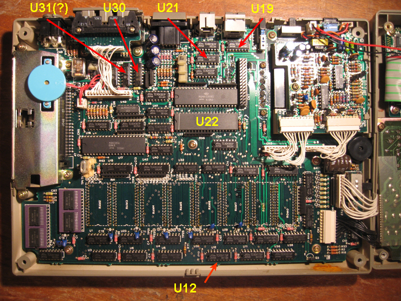
Figure 2. Location of TC 40H175p quad D-type flip-flop (U12)
With the PC-8201a connected to another computer via RS-232 and in Terminal Mode I checked 40H175p SEL A (from pin 14) and SEL B (from pin 11), this time with logic probe rather than a scope. SEL B showed LO, as indicated by a strong green light on my logic probe. SEL A, on the other hand, showed an orange light suggesting this line was pulsing. I checked the line with a voltmeter. It varied. Sometimes it was as low as 0.38v on a check and at other times as high as 2.7v!
I checked the inputs for this gate then looked up the truth tables from the TC 40H175p datasheet. Both SEL A and SEL B should be LO. SEL A certainly wasn’t.
I sent my input readings to Philip and he checked the U12 on his PC-8201a with the same configuration. He had the same inputs to the logic gate but his SEL A and B outputs were definitely both LO!
Confirmation
To confirm this line was the problem, we jumpered the SEL A line to ground (thereby forcing 0 volts) (Figure 3) AND restored UC21 and U19 to their normal state, by removing the jumpers and resoldering the cut pins.
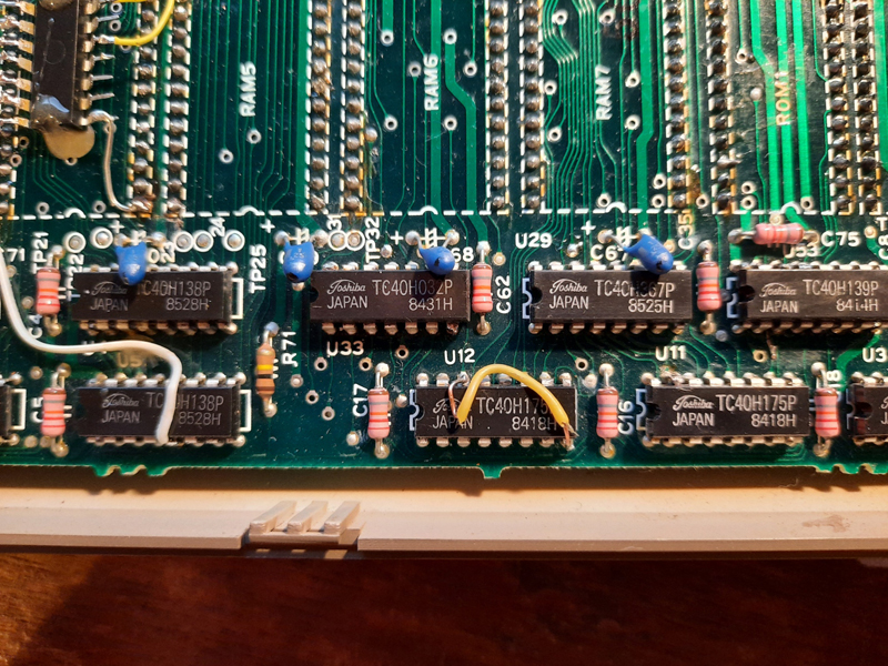
Figure 3. Forcing SEL A to zero volts by attaching it to ground
A test showed RS232 communications remained good, confirming that TC 40H175P (U12) was highly likely to be faulty component causing the issue.
Fix
Having diagnosed the fault the problem now was obtaining a new TC 40H175p. Eventually I found one on eBay.
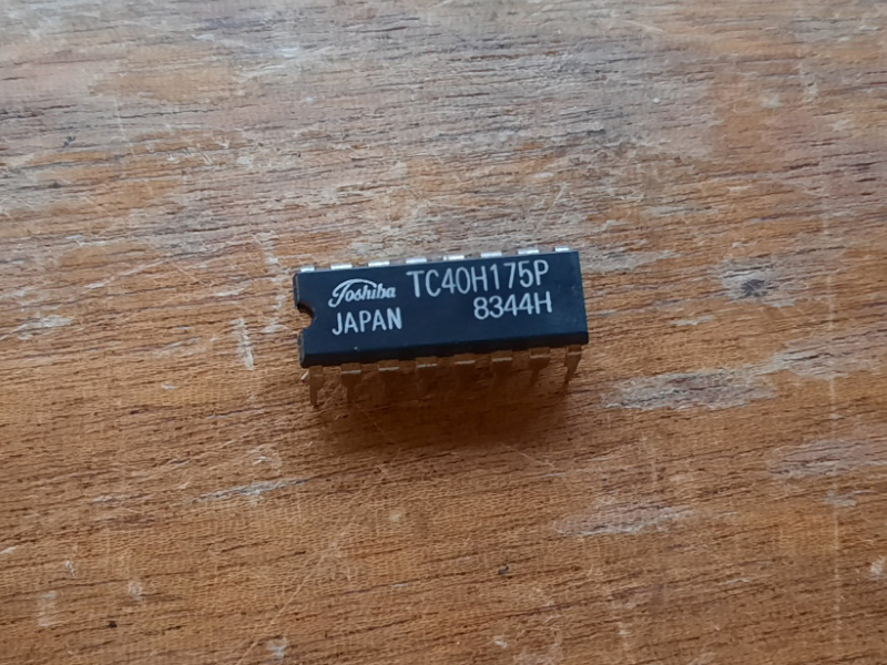
Figure 4. A new TC40H175P all the way from the U.K. via eBay
The shipping costs about 3 times the price of the IC, but this is one of the disadvantages of living in such a remote country. There was no local supply of these ICs or their equivalents.
Once the chip arrived, I snipped out the old one, removed the pins and solder (Figure 4), dropped the replacement in, then tested.
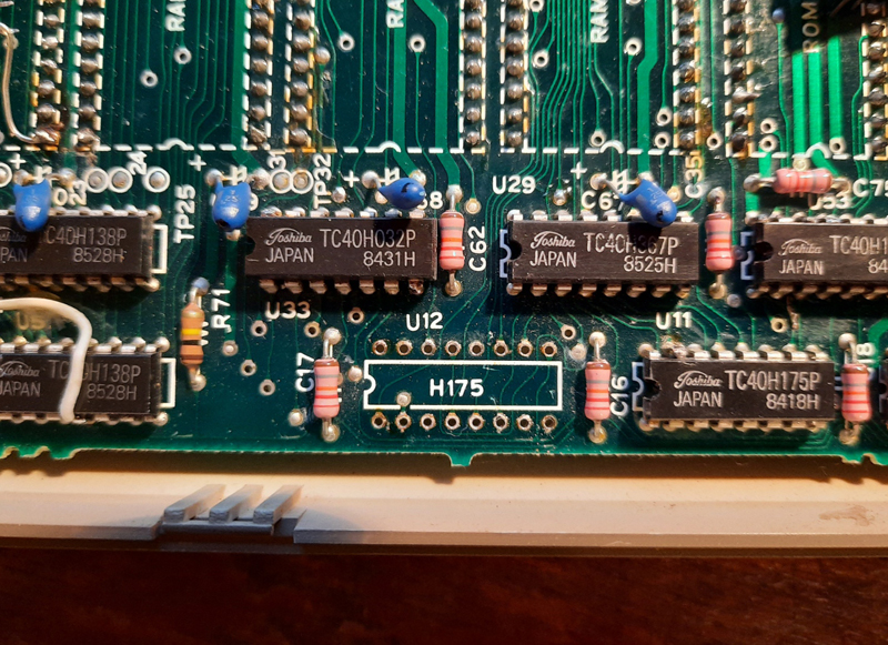
Figure 5. Ready for the replacement!
Communications worked like a charm, and the machine is now back to its old self. Problem solved!
Discussion
How had we missed the faulty SEL A line from U12 when we first looked at the problem? That line was checked with the scope and appeared to be 0v? The explanation is simple and is also a cautionary tale. I noticed the voltage on that line seemed to change every time it was checked. If by chance, the voltage was very low (say 0.38v) when we checked then this would hardly have been recorded on the scope. It would have looked like zero volts. Hence it was not picked up! It shows the value of using a logic probe over a scope for an initial check of logic gates.
Also, the troubleshooting part of the manual does not mention a faulty U12 as a likely candidate for RS-232 failure. However, once lines are traced back it clearly has a bearing on the process. Perhaps if it had been cited as a possible cause of RS-232 problems we would have paid it more attention during our first diagnostic session.
Anyway, all is good now. A big thank you to Philip Avery for his invaluable assistance with this project.
Terry Stewart
20th August, 2020